Modular temporary lighting assembly

a temporary lighting and module technology, applied in the direction of insulated conductors, coupling device connections, cables, etc., can solve the problems of often affecting the practicality of stringer removal

Active Publication Date: 2006-06-27
HOWELL JAY E
View PDF27 Cites 22 Cited by
  • Summary
  • Abstract
  • Description
  • Claims
  • Application Information

AI Technical Summary

Benefits of technology

[0012]One advantage of the present modular temporary lighting assembly is its ease of installation. Depending on the construction setting and the preferences of the workers, the assembly can be installed in at least two different ways. The assembly can be installed one section at a time, with each stinger being connected and each receptacle being hung before the next section of the assembly is installed. The assembly can also be installed by mounting each receptacle before the stringers are installed to connect the assembly together. Both methods of installation avoid the problems associated with conventional unitary lighting stringers that can be 100 feet in length. The individual components of the present assembly are less bulky and heavy so that they are easier to work with, particularly when the worker need to climb up and down a ladder. The worker also does not have to continuously untangle a long stringer as he or she hangs each of the integrally attached light fixtures.
[0013]Another advantage of the present modular temporary lighting system is its adaptability. The assembly can adapt to meet both the lighting needs of various construction settings and the changes in the lighting needs of a particular building during its construction. The assembly can be as short as ten feet or as long as is needed to properly light an area without overloading the temporary pedestal. Stringers that are initially hung to provide general lighting for a relatively open interior area can be easily rerouted or added onto to provide lighting to a specific area where detailed work is being done or to avoid an obstruction that is blocking its light from reaching that area. The modular lighting assembly does not become stuck or intertwined with other components as the construction of the interior progresses, which is particularly important when the interior rooms take form and the lighting needs change in each room. The assembly can be routed down a hallway or central area with branches of cord segments feeding off into individual rooms or specific areas. The assembly does not need to double back on itself to provide lighting to individual rooms or areas. As a result, fewer sections of cord, receptacles and light bulbs are needed to effectively light the interior of the building, and the assembly can easily reach the more remote areas of the building from the temporary pedestals. The reduction in sections of stringers, receptacles and light bulbs reduces load on the temporary pedestals, construction costs and any nuisance or safety hazard presented by the lighting assembly.
[0014]A further advantage of the present modular temporary lighting assembly is its reusability. Even when internal walls, plumbing and ductwork are built around the lighting assembly or it becomes intertwined with the electrical, fire alarm or telephone system or other components during construction, the modular system can be easily disassembled and removed for reuse. The stringers are simply unplugged from their corresponding receptacles so that both are easily removed without damage. The stringers and receptacles are then available for rerouting at the present construction site or reuse at a different construction project. Any individual stringer that becomes intertwined with the framing and permanent wiring systems can be cut and discarded without wasting the entire stringer assembly. The male plug and female outlet at the ends of each strand are significantly smaller than the receptacles and light fixtures so they are more easily removed. Still, should a single stringer need to be cut to quickly remove the temporary lighting assembly, the majority of the modular components of the assembly are easily removed without damage and are available for reuse.
[0015]A still further advantage of the present modular temporary lighting assembly is its durability and reliability. The assembly can withstand considerable physical and environmental abuse. The electric connections between the sections of cord and the receptacles are firm so that they are not jarred lose during rugged use. This durability and reliability is achieved without sacrificing the ease with which the assembly is installed, modified or removed. The twist-lock connections and durable construction of the individual components of the assembly do not require them to be preassembled by the manufacturer. As a result, attaching and removing the individual sections is a simple and productive task that helps reduce waist and construction costs and helps prevent unnecessary overloads to the temporary pedestals.
[0016]A still further advantage of the present modular temporary lighting assembly is its compliance with construction codes such as OSHA standard 29 C.F.R. 1926.405(a)(2) for Temporary Wiring, and National Electric Code Articles 305 and 527 for Temporary Wiring and Temporary Installation, respectively. The individual components, sections and the complete lighting assembly meet these code requirements because they are not designed for hard use, include receptacles with a twist lock outlet configurations that help prevent workers from plugging in tools and equipment with standard two or three-prong plug configurations. Were an OSHA representative to object to the use of receptacles with conventional twist lock outlets, the receptacles can be adapted to have a unique outlet configuration that would prevent workers from using a conventional adapter to connect a tool or piece of equipment to the temporary lighting system. Accordingly, the present invention should meet code requirements and be approved for temporary lighting applications, even when they are connected in series or in a multi-branch layout. The modular nature of the assembly eliminates or drastically reduces the need cut apart and then splice the stringers back together. In addition, the lamps allows light emission for a full 360 degrees, and can safely handle a 200 watt bulb so that the lighting capacity needed for a variety of construction settings are easily met.

Problems solved by technology

A problem with temporary construction lighting stringers is that they are used once and discarded.
The relatively large lighting fixtures frequently do not fit through the small openings between the wall framing and other components through which the electric cord of the stringer extends.
Removing the stringers is often rendered impractical without cutting or otherwise destroying the cord.
Yet, when the cord is cut, the entire stringer is rendered unusable.
While splicing the stringer back together may be permitted under Article 527.4(G), OSHA inspectors typically frown on temporary light stringers with numerous splices because of the increased safety risk the splices pose.
Yet, expensive temporary stringers that have been used on more than one job site often have many splice points, which increases the risk of a hazardous situation.
As a result, new stringers are needed for each construction site, and the waist is added in to the construction costs.
Unfortunately, workers and foremen can be unduly frugal with installing temporary lighting in order to keep costs to a minimum.
In some instances, the necessary stringers for appropriate lighting may only be installed after an accident occurs or a safety inspector requires additional lighting.
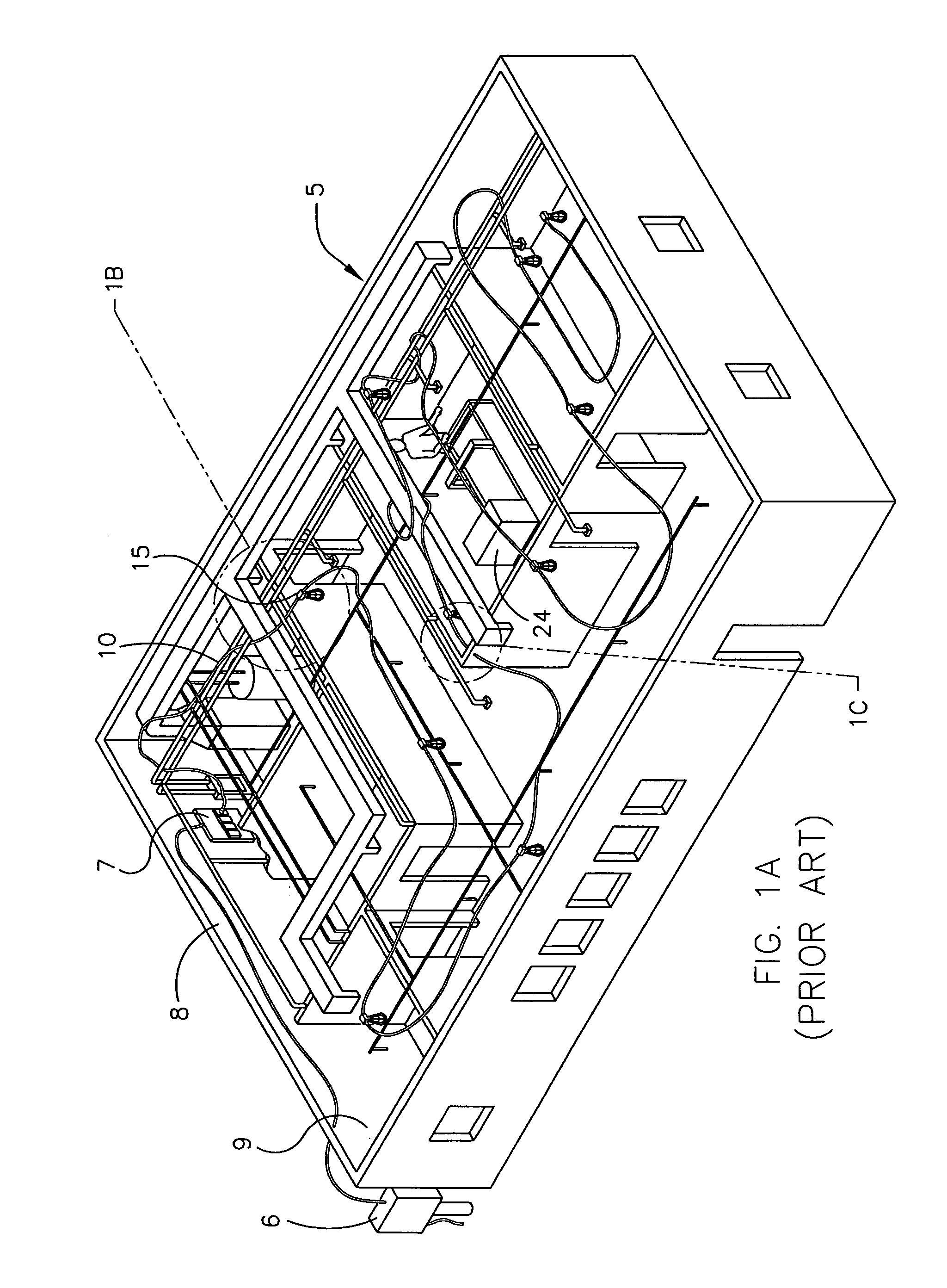
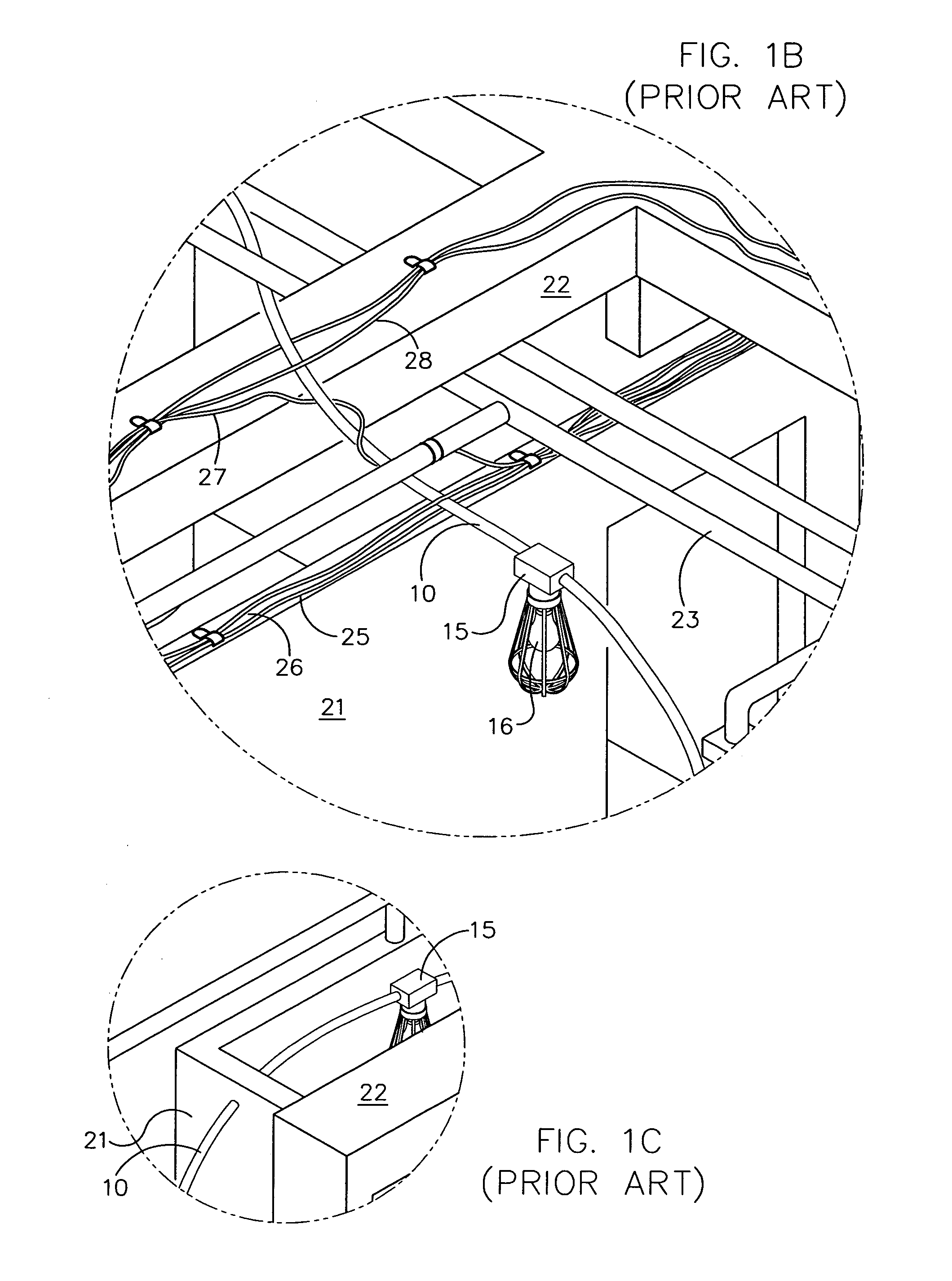
Another problem with conventional construction lighting stringers is that they come in a unitary strand having a length 50 to 100 feet.
These stringers are often too far from a specific area where detailed work needs to be done or become obscured by the interior walls and other components in the building.
Yet, the stringers can become stuck or intertwined with other components as the construction of the interior progresses.
The stringers cannot properly light the areas near the pedestal and the more remote rooms relative to the pedestal.
Although additional stringers can be plugged directly into the pedestal or into a receptacle at the end of an existing stringer, the additional stringers can overload the 20 amp breaker in the pedestal, increase construction costs and be a nuisance or safety hazard to the workers.
The additional stringers can be particularly troublesome when they are routed through doorways, walkways or openings used by the workers or overload the electrical capacity of a particular pedestal.
A further problem with construction lighting stringers is that they must be reliable and easy to install and remove.
Yet, the need for durability and reliability conflicts with the ease with which the stringers and fixtures are installed and removed.
Although some construction stringers have been developed to help remove the light fixtures, the fixtures are in practice too difficult to remove and properly reinstall in a safe and reliable manner.
These clamps must be opened to remove the fixture from the cord, which exposes the existing holes in the cord and creates a potential for a short circuit or safety risk if the holes are not properly covered due to an oversight due to a busy construction setting.
Should the knife slip, one of the electrical wires can be severed or the worker can be injured.
Reattachment is often unreliable because one or both of the contacts of the clamp do not pierce and firmly engage their respective wire.
As a result, workers typically view removing and reattaching the light fixtures as unproductive and simply add another stringer.
As noted above, adding new stringers in lieu of rerouting an existing stringer increases construction costs and can overload the pedestal breaker.
The additional stringers will also need to be cut and discarded at the end of the construction project if they become stuck or intertwined and difficult to remove.
A still further problem with construction lighting stringers is that they must comply with specific construction code requirements such as the OSHA standard 29 C.F.R. 1926.405(a)(2) for Temporary Wiring, and the National Electric Code Articles 305 and 527 for Temporary Wiring and Temporary Installations, respectively.
The codes also prohibit temporary lighting from have receptacles, particularly if the temporary lighting system has an ungrounded conductor.
Conventional trouble lights are not appropriate for construction settings because they do not comply with OSHA and National Electric Code requirements.
The cord is not physically tough enough, so that the cord and its conductive wires could be damaged or cut should the cord be struck by a hammer or passed over a sharp edge.
The standard outlet configuration allows workers to plug in a tool or piece of equipment with a standard prong configuration into the receptacle of the trouble light, which creates a potential safety hazard.
The wiring or circuitry of the trouble light could overheat or short circuit, and cause a blackout or fire.
In addition, trouble lights do not provide the necessary lighting capacity needed for a construction setting.
For these and other reasons, trouble lights would not be appropriate or approved for temporary lighting applications under Article 527.2(B) for the vast majority if not all construction conditions, particularly if they were connected in series or in a multi-branch layout.

Method used


Image

  • Modular temporary lighting assembly
  • Modular temporary lighting assembly
  • Modular temporary lighting assembly

Examples


Embodiment Construction

[0027]While this invention is susceptible of embodiments in many different forms, the drawings show and the specification describes in detail a preferred embodiment of the invention. It should be understood that the drawings and specification are to be considered an exemplification of the principles of the invention. They are not intended to limit the broad aspects of the invention to the embodiment illustrated.

[0028]Toward the beginning of the construction of a building 5, a local electric utility company hooks up a temporary service box 6 to provide electric power to the construction site shown in FIG. 1. One or more temporary pedestals 7 are electrically connected to the service box 6. The pedestals 7 are typically located on the inside of an outer wall 8. The outer walls 8 and roof define the interior 9 of the building 5. During the construction of the interior 9 of the building 5, one or more conventional temporary lighting stringer 10 are installed to provide the necessary lig...


PUM


Abstract

The present invention pertains to a modular temporary lighting assembly and multi-outlet stringer that is particularly suited for building construction settings. The modular lighting assembly is formed by connecting a plurality of like-shaped stringers and a plurality of like-shaped multi-outlet receptacles. The assembly is formed by several sections, with each section including one stringer and one receptacle. Each stringer has a three-prong twist-lock plug at one end, and a three-port twist-lock outlet at the other. Each receptacle has a light socket, one male twist-lock plug, three female twist-lock outlets, and a mounting hook. The socket receives a light bulb and a removable protection cage. The receptacles are hung along the ceiling of the building and electrically connected by the stringers. The sections of the lighting assembly are connected in a single linear routing or a multi-branch pattern throughout the desired areas of the building. Each receptacle has a supply stringer that supplies it with electric power, and two or more feed stringers that supply power to other receptacles.

Description

CROSS-REFERENCE TO RELATED APPLICATION[0001]The present invention is based on and claims priority to U.S. Provisional Patent Application Ser. No. 60 / 480,340 filed on Jun. 20, 2003.TECHNICAL FIELD OF THE INVENTION[0002]The present invention relates to a modular temporary lighting assembly that is particularly suited for building construction settings to light the interior of the building, is easy to install in a variety of routing configurations that can be modified during construction, and is easy to remove for reuse even when a section of the assembly becomes intertwined with or blocked by permanent building components.BACKGROUND OF THE INVENTION[0003]The construction of a building requires the coordination of a variety of specialized work. The ground is excavated and the foundation is poured. The outer walls and roof are erected, and the framing of the interior walls are roughed in. The plumbing, electrical wiring, heating and ventilation, and other concealed or built in component...

Claims


Application Information

Patent Timeline
Patent Type & Authority Patents(United States)
IPC IPC(8): F21S4/00F21S2/00F21V15/02H01R31/02H01R33/92H02G3/00
CPCH02G3/00H01R33/92F21S2/00F21V15/02H01R31/02
Inventor HOWELL, JAY E.
Owner HOWELL JAY E
Why Eureka
Try Eureka