

Disc spring centering device for squeeze film dampers
Patent Information
- Authority / Receiving Office
- US · United States
- Patent Type
- Patents(United States)
- Current Assignee / Owner
- LUFKIN GEARS LLC
- Publication Date
- 2006-06-27
Smart Images
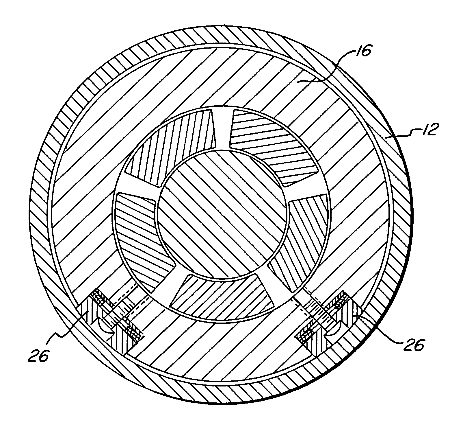
Figure 1 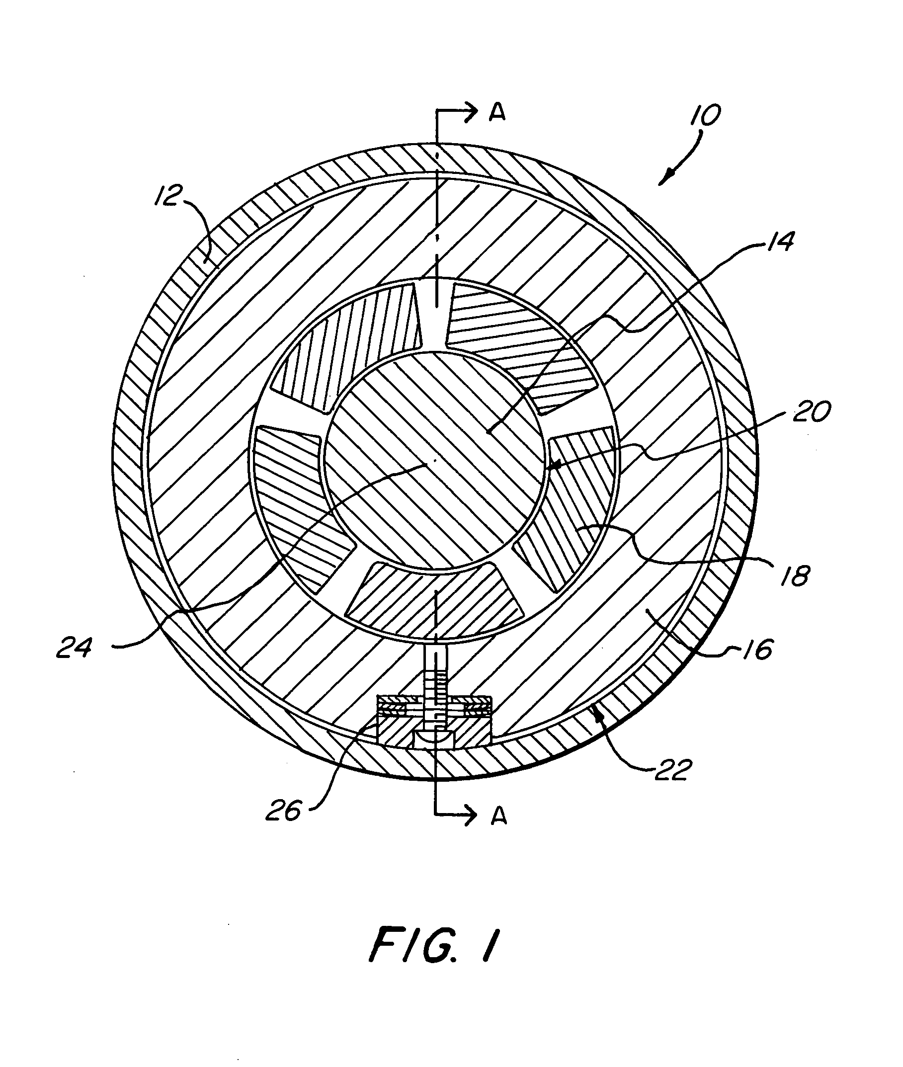
Figure 2 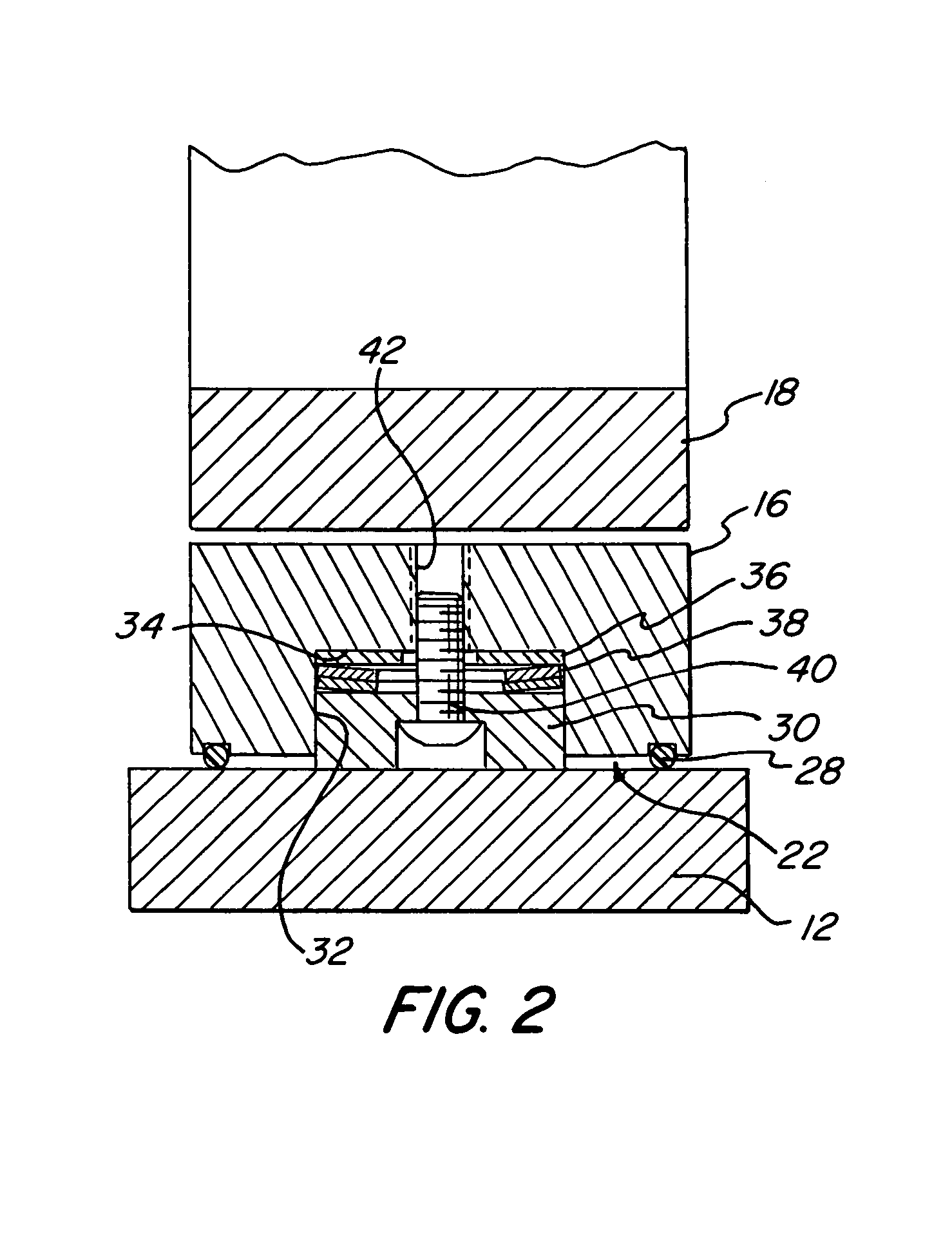
Figure 3
Abstract
Description
FIELD OF THE INVENTION
[0001] The present invention relates generally to bearings of the type which are typically used in connection with high speed rotating shafts, and more specifically to such bearings which incorporate squeeze film damper bearing support systems for attenuating vibrations within the bearings.BACKGROUND OF THE INVENTION
[0002] Squeeze film dampers have been used for years to add damping to rotor-bearing systems for vibration attenuation. In such systems, a thin oil film between the journal bearing housing and the bearing case provides damping by allowing the bearing housing to bounce around in the bearing case or adapter ring (hereinafter collectively referred to as “bearing case”) within the oil film. The squeeze effect on the oil produces the damping.
[0003] One challenging aspect of squeeze film damper design concerns centering the bearing housing in the bearing case. Elastomer O-rings are often used for this purpose. O-ring grooves provided in the bearing housing a...