Intervertebral disk replacement

a technology of intervertebral disks and prostheses, which is applied in the direction of prosthesis, osteosynthesis devices, ligaments, etc., can solve the problems of thinning, weakening and cracking of the outer layer, and affecting the stability of the inner layer, so as to achieve near and long-term post-implantation stability

Inactive Publication Date: 2006-06-27
DICKMAN CURTIS A
View PDF3 Cites 249 Cited by
  • Summary
  • Abstract
  • Description
  • Claims
  • Application Information

AI Technical Summary

Benefits of technology

[0029]In essence, the intervertebral disk is an anatomical spacer, stabilizer, load dampener and shock absorber, positioned between the vertebral end plates. The disk and surrounding ligaments also stabilize the spine, connect adjacent vertebrae, and prevent excessive rotation and subluxation of the vertebrae. As noted in the background section above, intervertebral disks have some desirable deformability attributable to their viscoelastic properties. They also demonstrate hysteresis, and have a high degree of hydration. The hysteresis is exhibited in response to the mild deformability of the disk under compressive loading, when, after unloading, the disk rebounds to its normal position. This resiliency to compressive loading and unloading is a key function of the disk. To yield suitable results, an artificial disk—a disk prosthesis—must replicate all of these properties, characteristics or functions of the natural intervertebral disk.
[0031]The intervertebral disk prosthesis of the invention possesses characteristics of being compressible, mildly deformable, resilient, hydrated, durable, nontoxic, nondegradable, nonfragmenting, and viscoelastic, among other properties. The prosthesis acts as a solid material to provide structural spacing and load dampening effect between vertebral end plates. It is suitable for replacement of a damaged natural disk in any of the cervical, thoracic or lumber spinal regions of the vertebral column.

Problems solved by technology

Injury, exertion or the aging process can produce changes in the disks, such as loss of firmness of the central region and thinning, weakening and cracking of the outer layer as a result of degenerative changes, and breakage of the outer layer and squeezing out of the central region as a result of injury from external pressure or heavy lifting.
The result is chronic lower back or leg pain, which can be disabling.
While fusion enjoys success in alleviating symptoms and stabilizing the joint at the previous vertebra-disk interface, it decreases the range of motion of the vertebral column in the portion of the region where the surgical procedure was performed.
Also, the biomechanical rigidity of the fused vertebrae may exacerbate deterioration of adjacent portions of the region.
However, so far as is known to the applicant herein, the prior art has not given promise of successful implementations and methods for anchoring implanted artificial intervertebral disks in the vertebral column to achieve relatively permanent fixation and stabilization of the implant.
Prior art artificial intervertebral disks, and techniques of fastening, anchoring and stabilizing implanted artificial disks do not appear likely to yield satisfactory results.

Method used


Image

  • Intervertebral disk replacement
  • Intervertebral disk replacement
  • Intervertebral disk replacement

Examples


Embodiment Construction

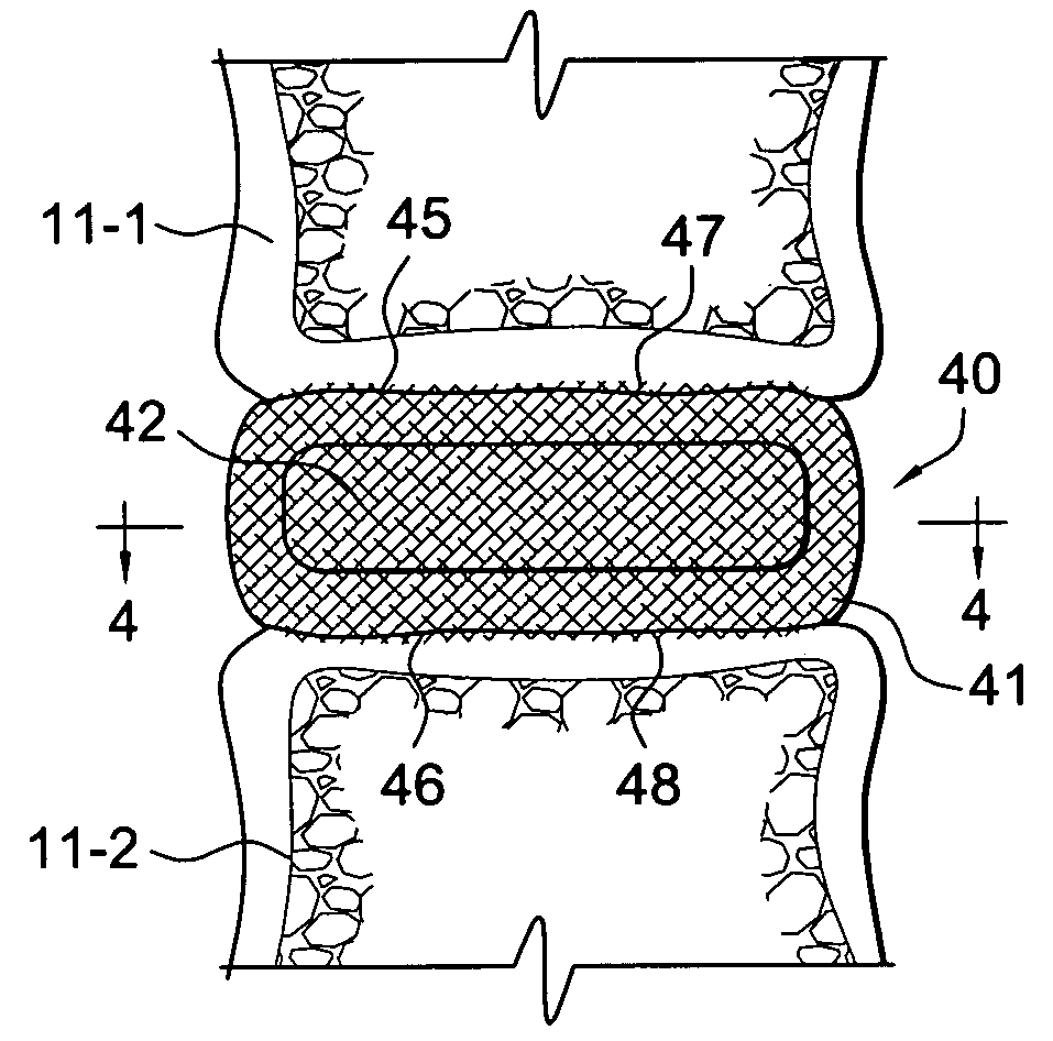
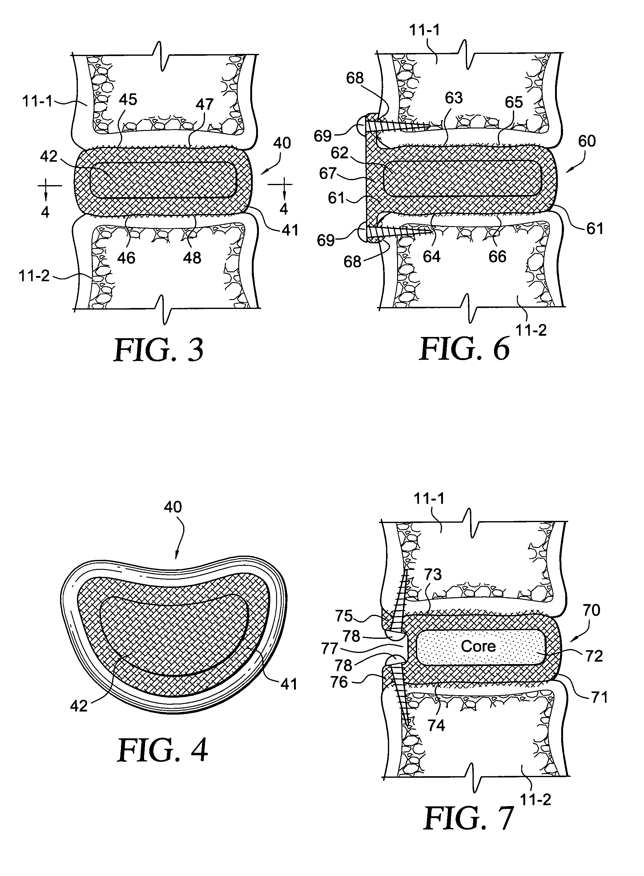
[0047]Referring to FIGS. 3 and 4, a presently preferred embodiment is a unified composite disk prosthesis 40, shown as being positioned following implantation between the bodies of two vertebrae11-1 and 11-2 of the vertebral column, as viewed anteriorly (FIG. 3). Prosthesis 40 includes a matrix 41 with a substrate of bioincorporable continuous fabric. In its central region, the substrate is impregnated with a liquid or semi-liquid polymer—preferably a hydrogel polymer—that intermixes with the substrate fabric in that region to form a nuclear core (nucleus) 42. This core is a hybrid composite of the two materials, a central mix of polymer and fabric that is elastically deformable and accurately mimics the nucleus pulposus of a native or natural disk.

[0048]The polymer is preferably an injectable, curable liquid that, after injection into the central region of the substrate, sets to form a viscoelastic solid. Alternatively, the liquid may be soaked into the fabric at the central region...


PUM

PropertyMeasurementUnit
shapeaaaaaaaaaa
viscoelasticaaaaaaaaaa
tensile strengthaaaaaaaaaa

Abstract

An intervertebral disk prosthesis in a preferred embodiment has a matrix of bioincorporable fabric, and a nuclear core centrally mixed into the matrix. The core is formed by impregnating the fabric substrate centrally with a polymer, preferably of liquid form that cures into a viscoelastic solid, in which each component—polymer and fabric—reinforces the other against tearing, shearing and weakening under stress. The core is a hybrid composite adapted for elastic deformation centrally of the matrix, in which the polymer is mixed with the fabric, and is surrounded by the outer bioincorporable fabric margin of the matrix. In another embodiment, the nuclear core is separated from an outer sheath of the bioincorporable fabric by an intermediate ligament encasement that surrounds the purely polymeric core In either embodiment, each edge of the outer fabric that interfaces a vertebral end plate is impregnated with an agent to stimulate osseus incorporation and anchoring. An adjunct anchoring system with penetration of bone of adjacent vertebra may be used to for attachment until and after bioincorporation occurs.

Description

BACKGROUND OF THE INVENTION[0001]The present invention relates generally to intervertebral disk prostheses, and more particularly to improvements in and anchoring systems for disk prostheses to assure operation, fixation and stabilization of the prosthesis corresponding to a natural disk.[0002]The human backbone (the vertebral or spinal column) 10 (FIG. 1) consists of numerous longitudinally aligned vertebrae 11, adjacent ones of which are separated by individual cartilaginous intervertebral disks 12 and connected to one another by ligaments. The vertebral column is the vertical axis of the skeleton, extending from the skull (not show) at its proximal end to the pelvis (not shown) at the distal end. It serves to support the head and trunk of the body, and to protect the spinal cord (not shown) that passes through the vertebral (spinal) canal formed by openings in the vertebrae. Adjacent the distal end of the vertebral column, the sacrum portion 13 of the pelvis is formed by several ...

Claims


Application Information

Patent Timeline
Patent Type & Authority Patents(United States)
IPC IPC(8): A61F2/44
CPCA61F2/441A61F2/442A61B17/7062A61F2310/00976A61F2/30965A61F2/4425A61F2002/2817A61F2002/30062A61F2002/30133A61F2002/30383A61F2002/30578A61F2002/30583A61F2002/30884A61F2210/0004A61F2210/0085A61F2220/0025A61F2230/0015A61F2310/00023A61F2310/00293A61F2310/00365A61F2310/00796A61F2/08
Inventor DICKMAN, CURTIS A.
Owner DICKMAN CURTIS A
Why Eureka
Try Eureka