Electronic ballast with overvoltage monitoring

a technology of overvoltage monitoring and electronic ballast, which is applied in the direction of electric variable regulation, process and machine control, instruments, etc., can solve the problems of apparatus destruction, inconsiderable power consumption, and no end to end consumption of not inconsiderable amount of power

Inactive Publication Date: 2006-06-27
TRIDONIKATKO GMBKH & KO KG
View PDF12 Cites 1 Cited by
  • Summary
  • Abstract
  • Description
  • Claims
  • Application Information

AI Technical Summary

Benefits of technology

[0008]This object is achieved by means of an electronic ballast which has an overvoltage monitoring device, which monitors the supply voltage delivered to the electronic ballast and, in the event that the supply voltage exceeds a predetermined nominal value, initiates an optically or acoustically perceptible warning signal. The ballast is thus itself not in a position to act to counter the overvoltage. Instead of this it is ensured that the fault in the voltage supply is indicated directly after the switching on of the lamp, so that appropriate measures can be taken to remove the overvoltage. By means of the measures in accordance with the invention the operational security of the ballast is thus significantly increased.
[0009]Further developments of the invention are also described and claimed herein. For example, an input signal is delivered to the overvoltage monitoring device. This input signal preferably may be the supply voltage rectified by a rectifier circuit on an input side of the ballast. The detected signal is then compared, with the aid of a comparator, with a nominal value. Alternatively to a simple comparator, there may, however, also be provided an analogue / digital converter, which converts the detected measurement value into a digital value consisting of at least two bits, through which the exactitude of the overvoltage monitoring is increased.
[0010]Preferably, upon recognition of an overvoltage condition, the overvoltage monitoring device sends a corresponding signal to a control circuit which is provided for the control of the inverter of the ballast, whereby the control circuit, as reaction to the received overvoltage signal, periodically switches the lamp on and off or periodically modulates the brightness of the lamp. A particularly elegant development of the invention consists in generating the periodic brightness variation of the lamp in that the regulation circuit for the operation of the inverter is influenced. For example, if the control circuit detects an operating parameter of the load circuit, compares this with a reference value, and generates in dependence upon the comparison result control signals for controlling the inverter, it can thus be provided that the reference value of the regulation circuit is periodically altered. Through the alteration of the reference value, the lamp is automatically operated with a modulated brightness, without particular measures being necessary for this purpose.
[0011]A further development of the invention incorporates a digital regulation circuit. This involves providing, in the control circuit, an analogue / digital converter for converting the detected operating parameter of the load circuit into a digital value consisting of at least two bits, whereby the control circuit calculates on the basis of this digital value, in a digital regulation circuit, switching information for the operation of the inverter and passes this on to a driver circuit which converts the switching information into corresponding control signals for the operation of the inverter. The analogue / digital converter may then operate in time multiplex mode and be employed at regular intervals also for the detection and the evaluation of the supply voltage. This variant makes possible an integration of the overall ballast to the greatest possible extent, since the components of the control circuit are integrated into a single circuit and at the same time can be used also for realisation of the overvoltage monitoring. In particular it can be provided that the control circuit is constituted as an application specific integrated circuit (ASIC).

Problems solved by technology

This overvoltage brings with it the danger that the apparatuses could be destroyed if the causes of the faulty wiring are not removed in a timely manner.
Although there would be the possibility of so configuring the ballasts that they self-actingly compensate the overvoltage, through this however a not inconsiderable amount of power would be consumed to no end.

Method used


Image

  • Electronic ballast with overvoltage monitoring
  • Electronic ballast with overvoltage monitoring

Examples


Embodiment Construction

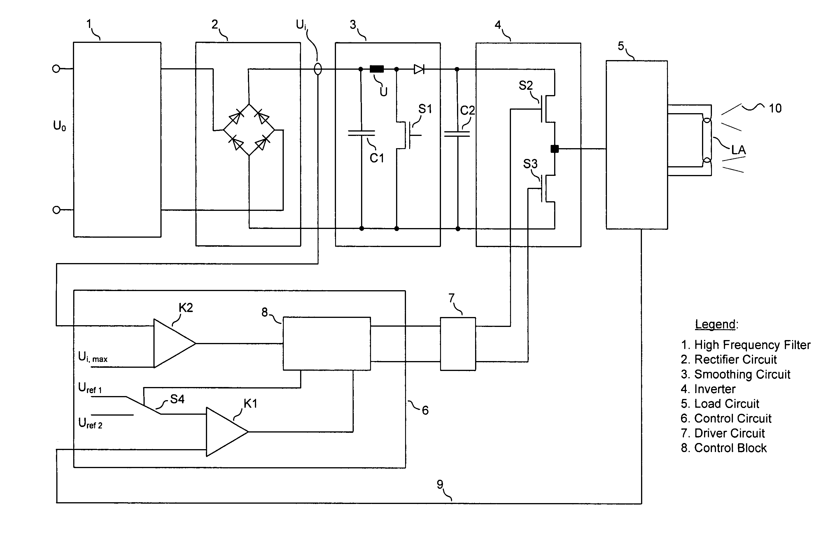
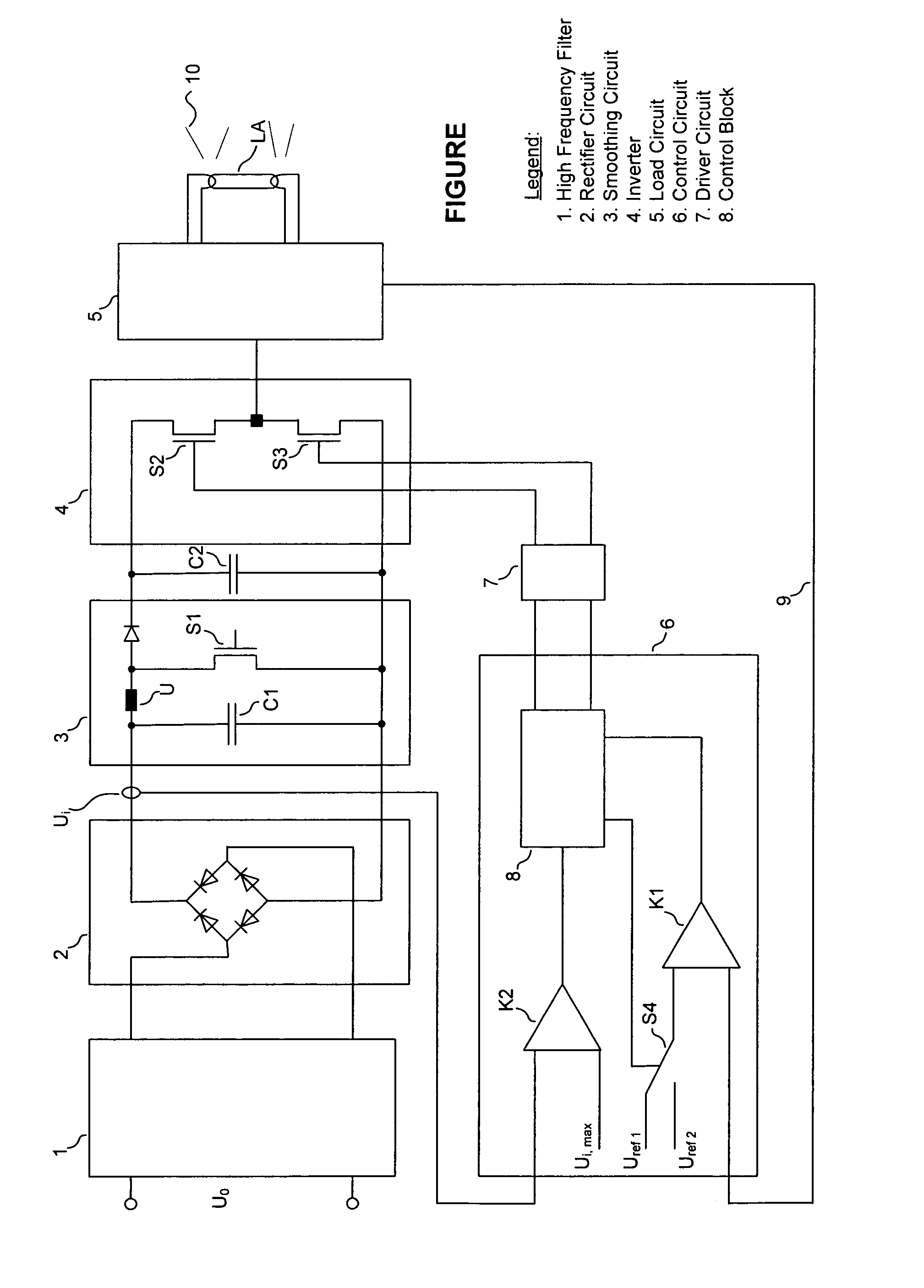
[0013]The ballast illustrated in the single FIGURE is connected on the input side to the mains voltage supply U0 via a high frequency filter 1. At the output of the high frequency filter 1 there is a rectifier circuit 2 in the form of a full-bridge rectifier, which converts the mains supply voltage U0 into a rectified input voltage Ui for a smoothing circuit 3. the smoothing circuit 3 serves for filtering harmonics and smoothing the input voltage Ui and includes a smoothing capacitor C1 and a step-up device having an inductance L1, a controllable switch in the form of a MOS field effect transistor S1 and a diode D1. In place of the step-up unit, also other known smoothing circuits can be employed.

[0014]By means of an appropriate switching of the MOS field effect transistor S1 there is generated an intermediate circuit voltage applied via the storage capacitor C2 following the smoothing circuit 3, which intermediate circuit voltage is supplied to the inverter 4. This inverter 4 is co...


PUM


Abstract

An electronic ballast for at least one gas discharge lamp (LA), preferably for a fluorescent tube, having a rectifier circuit (2) connectable to a supply voltage source, a smoothing circuit (3) connected to the output of the rectifier circuit (2) for generating an intermediate circuit voltage (UZ), and an inverter (4), fed with the intermediate circuit voltage (UZ), to the output of which a terminal for the load circuit (5) containing the lamp (LA) is connected, and an overvoltage monitoring device which monitors the supply voltage (U0) delivered to the electronic ballast, whereby in the event that the supply voltage exceeds a predetermined nominal value (Ui,max), an optically or acoustically perceptible warning signal is issued.

Description

CROSS REFERENCE TO RELATED APPLICATONS[0001]This is a Continuation of International Application PCT / EP02 / 11422 filed on Oct. 11, 2002, which was published on Jul. 3, 2003 in German, but not English, as WO 03 / 055281 A1, the priority of which is hereby claimed and which claims the priority of German application 101 63 034.4 filed Dec. 20, 2001, the priority of which is also claimed herein.BACKGROUND OF THE INVENTION[0002]1. Field of the Invention[0003]The present invention relates to an electronic ballast for the operation of at least one gas discharge lamp.[0004]2. Description of the Related Art[0005]If a plurality of electronic ballasts for the operation of gas discharge lamps are wired together to form a larger illumination system, normally the phase terminals and the neutral lines of the ballasts are first connected with one another and then connected to the mains. If the common connection of the neutral lines of the ballasts is not or is only insufficiently connected with the mai...

Claims


Application Information

Patent Timeline
Patent Type & Authority Patents(United States)
IPC IPC(8): H05B37/02H01J1/60H02H11/00H05B41/285
CPCH05B41/2853H02H11/007
Inventor SOEHNEL, CHRISTIAN
Owner TRIDONIKATKO GMBKH & KO KG
Why Eureka
Try Eureka