
Series charger with separate detection of batteries (battery set)

a charger and battery technology, applied in the field of chargers, can solve the problems of lowering the service life of the charger, not being fully charged while the other is not, and still not reaching the expected effect, etc., and achieves the effects of high use safety, rapid charging, and small volum

Inactive Publication Date: 2006-06-27
YANG FU I
View PDF2 Cites 44 Cited by
  • Summary
  • Abstract
  • Description
  • Claims
  • Application Information

AI Technical Summary

Benefits of technology

[0011]Therefore, it is a primary object of the present invention to eliminate the aforementioned drawbacks and to provide a series charger with separate detection of batteries (battery set) which meets the market requirements, is rapidly charged, has high use safety, small volume and achieves the largest charging capacity.

Problems solved by technology

However, they still can't reach the expected effect and need to be improved.
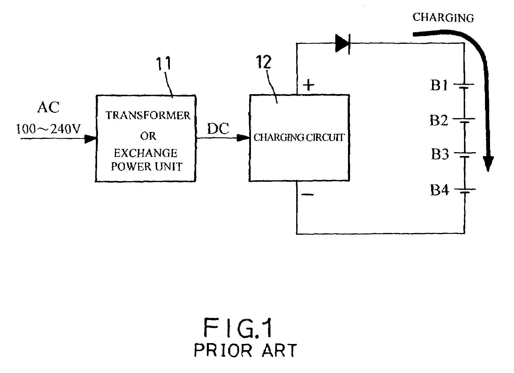
However, its disadvantage lies in that one is fully charged while the other is not.
This will easily lead to overcharge of the full-charged battery when the charging process is continued, thereby lowering its service life.
However, the voltage of the not-fully-charged battery still rises.
In case of abnormality of one battery, an unexpected danger could happen.
Besides, another disadvantage of the series charger lies in that single battery can't be charged.
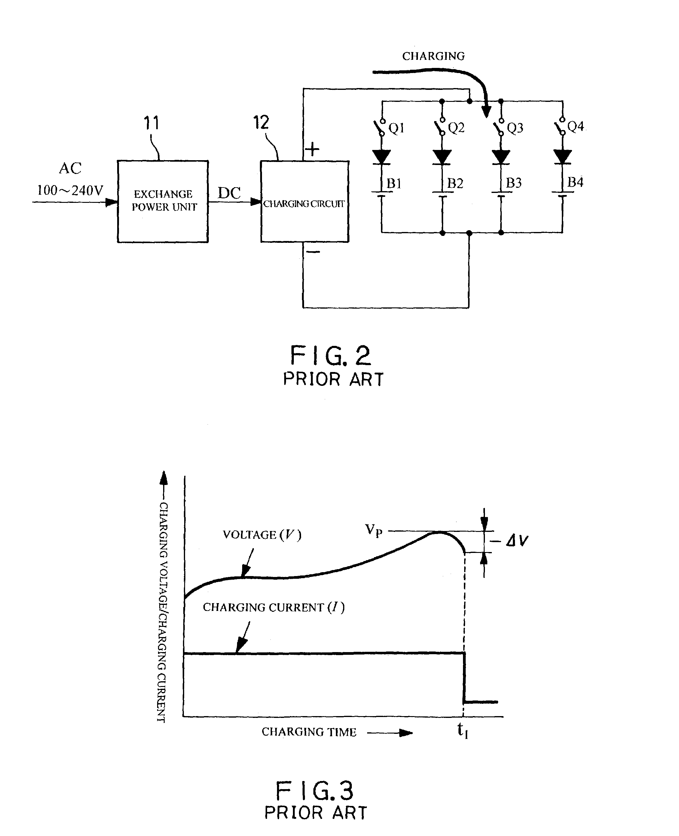
However, the greatest disadvantage of the parallel charger lies in that it can't meet the requirements of speedy charging because the choice and the installation of the electronic control elements are difficult.
Supposed that the charging voltage is 2V, and the charging current of each parallel-connected battery is 1.5 A, the required total current will be 6 A. However, the diode of the electronic components has problem with internal resistance while the transistor has problem with pressure difference.
For example, it's difficult to fulfill the safety requirement that the wiring of the circuit board has to amount to over 6 mm.
Thus, the volume of the parallel charger can't be reduced.
Moreover, the components are easily over-heated.
Furthermore, the rapid charging requirement can't be fulfilled.
And to add cooling elements will increase the whole volume and the material cost.

Method used


Image

  • Series charger with separate detection of batteries (battery set)
  • Series charger with separate detection of batteries (battery set)
  • Series charger with separate detection of batteries (battery set)

Examples


Embodiment Construction

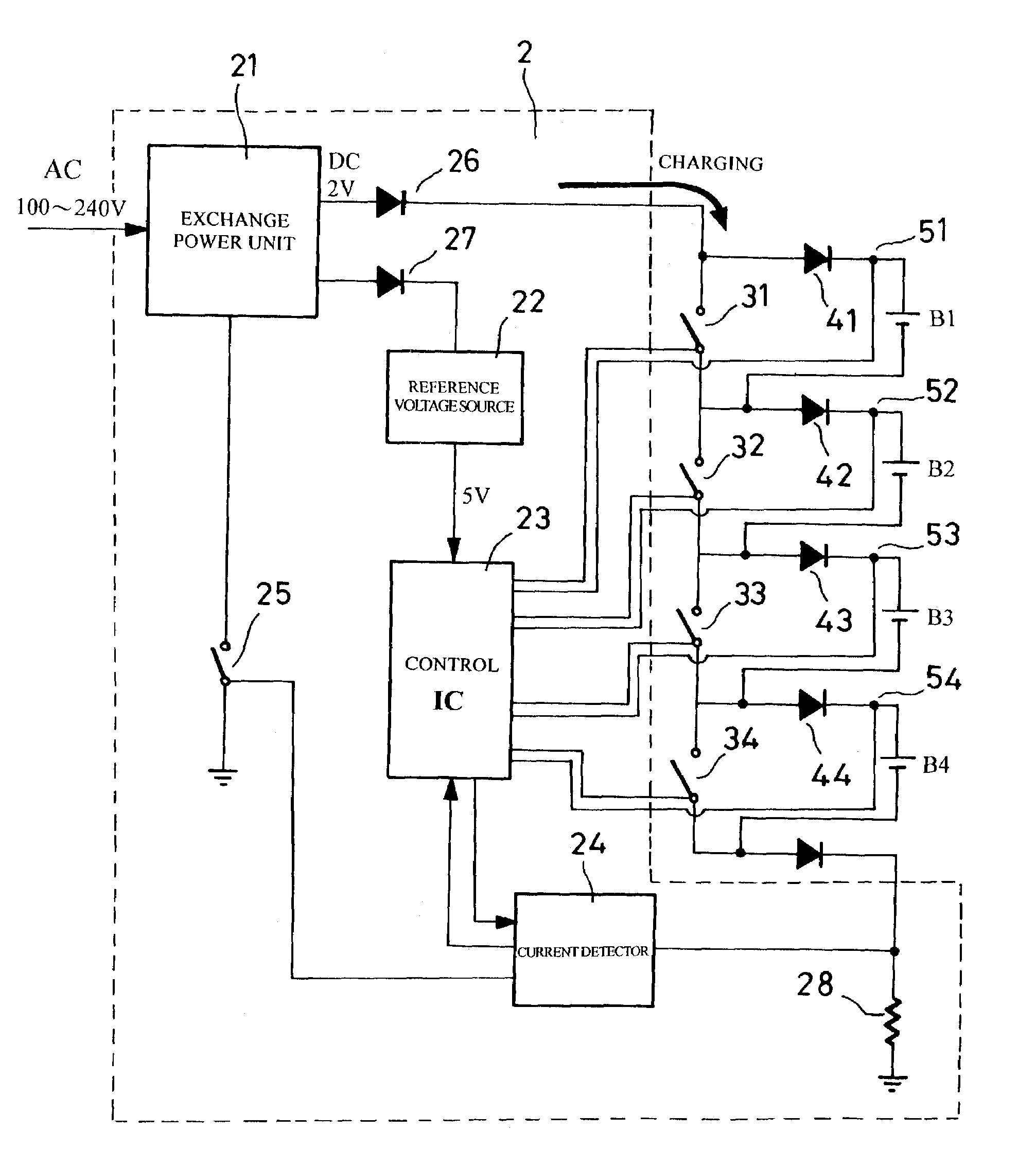
[0024]First of all, referring to FIG. 4, a block diagram of main components of the charger of the present invention which includes:

[0025]a charging control device 2 having an exchange power unit 21 for converting the inputted AC power into DC power so as to charging four batteries B1 through B4 in series connection, the charging control device 2 further providing a reference voltage source 22 to a control IC 23 which is connected with a current detector 24 for measuring the current value of the batteries; and

[0026]each of the series-connected batteries B1 through B4 being parallel-connected with a switch element 31, 32, 33, 34, a one-way diode 41, 42, 43, 44 being interposed between the positive end of the batteries and each of the switch elements 31, 32, 33, 34.

[0027]The control IC 23 provides −ΔV to the positive terminal of the respective charging circuit of the batteries for detecting the end-point voltage thereof. Moreover, the charging current, as illustrated in FIG. 4, flows t...


PUM


Abstract

The present invention relates to a series charger with separate detection of batteries which includes a charging control device for converting the inputted AC power into DC power so as to charging four batteries in series connection. The charging control device further provides a reference voltage source to a control IC which is connected with a current detector for measuring the current value of the batteries. Each of the series-connected batteries is parallel-connected with a switch element. A one-way diode is interposed between the positive end of the batteries and each of the switch elements. Besides, the control IC provides −ΔV to the positive terminal of the respective charging circuit of the batteries for detecting the end-point voltage thereof. When each of the batteries is fully charged, the respective switch element is switched in a close circuit so that the charging current continues to flow downward for further charging operation. Moreover, after all batteries are fully charged one after another, the current detector is used to regulate the charging current or the switch-on time of the switch elements is controlled for proceeding with supplementary charging procedure.

Description

RELATED PATENT APPLICATIONS[0001]This patent application is a continuation-in-part of Ser. No. 10 / 350,064, filed on 24 Jan. 2003, now U.S. Pat. No. 6,784,638.BACKGROUND OF THE INVENTION[0002]1. Field of the Invention[0003]The present invention relates to a charger for NiH / NiCd secondary batteries, and more particularly, to a charger through which a plurality of batteries in series connection can be charged. Moreover, a control IC (integrated circuit) and a detection circuit are utilized to detect and control every battery (battery set) in series connection.[0004]2. Description of the Prior Art[0005]Since portable electronic products, such as digital cameras, game players, etc. become more and more popular, a greater capacity of secondary batteries is more required. In addition, the charging time is preferably shorter and the charger's volume is preferably smaller. Therefore, a smaller and cheaper feature with shorter charging time and longer service life is the common requirements o...

Claims


Application Information

Patent Timeline
IPC IPC(8): H02J7/00
CPCH02J7/0016
Inventor YANG, FU-I
Owner YANG FU I
Learn More