
Integrated digital calibration circuit and digital to analog converter (DAC)

a digital calibration circuit and digital converter technology, applied in the field of integrated digital calibration circuits and digital to analog converters, can solve the problems of limiting performance, less reliable, and high cost, and achieve the effects of reducing external control circuit demands, reducing errors, and improving accuracy

Inactive Publication Date: 2006-06-27
ANALOG DEVICES INC
View PDF28 Cites 15 Cited by
  • Summary
  • Abstract
  • Description
  • Claims
  • Application Information

AI Technical Summary

Benefits of technology

[0006]It is a further object of this invention to provide an improved integrated programmable digital calibration circuit and digital to analog converter (DAC) which provides accuracy and performance while maintaining lower cost and complexity.
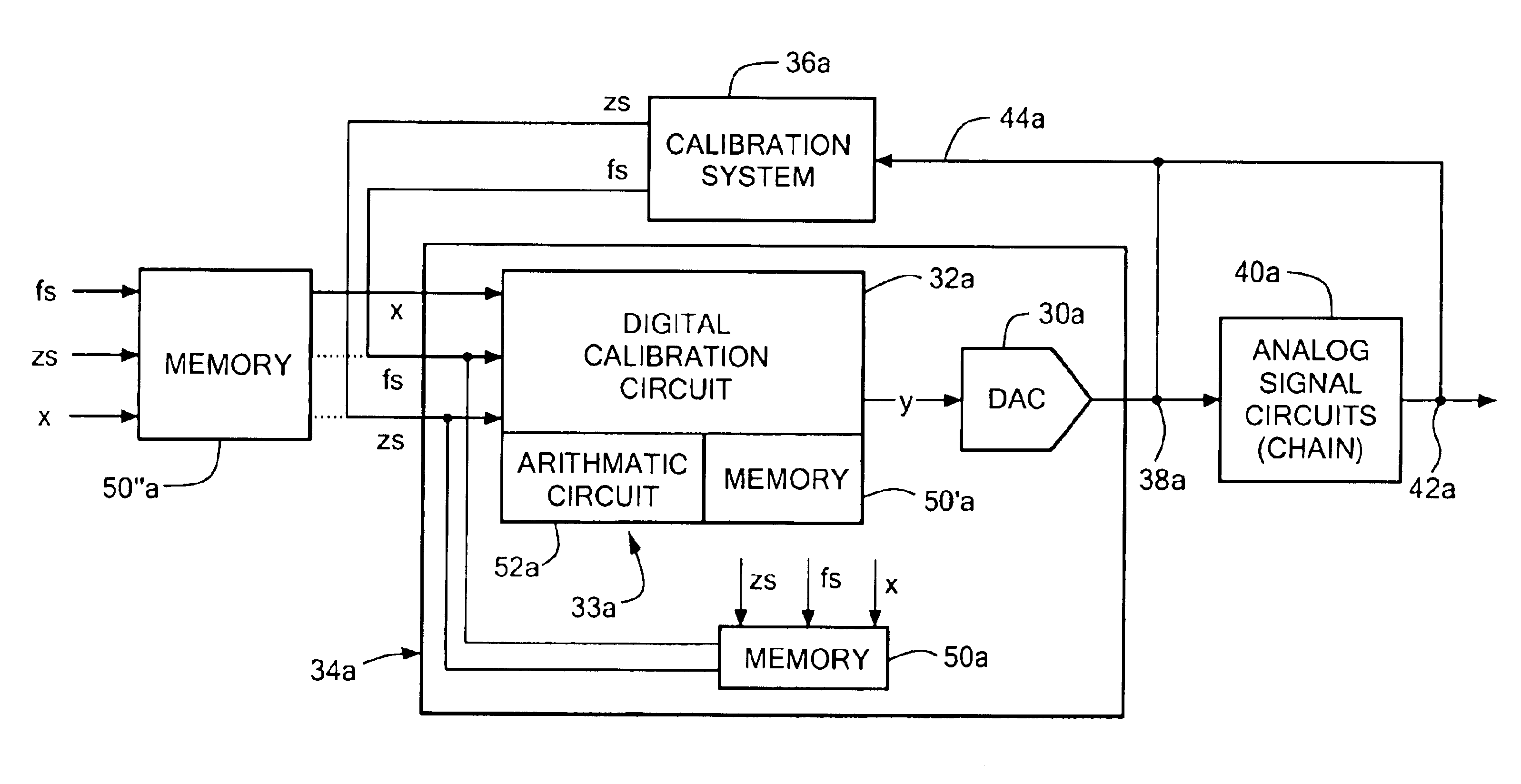
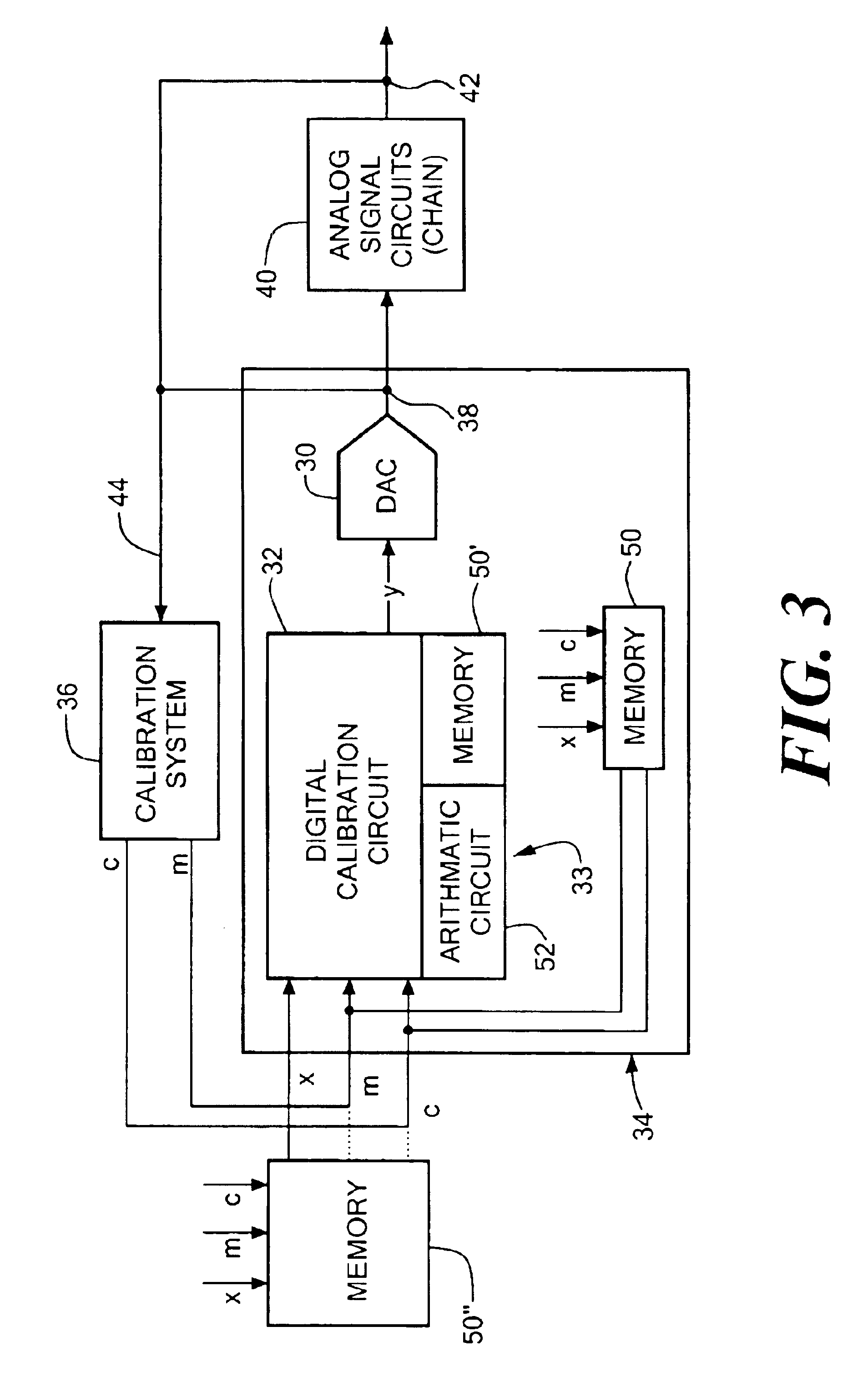
[0017]The invention results from the realization that a simple and inexpensive, but much more accurate, DAC can be achieved by integrating a calibration unit with the DAC to provide the DAC transfer function end point coefficients, e.g. gain and offset coefficients, zero scale and full scale coefficients, digitally, to the DAC, which coefficients can be stored externally or internally, on the calibration circuit or on a chip which holds both the calibration circuit and the DAC, and can be applied to adjust the DAC end points or the DAC end points and the end points of the analog circuits associated with the DAC and further the memory can be made user accessible for post fabrication error correction programming for the DAC and / or associated analog circuits.

Problems solved by technology

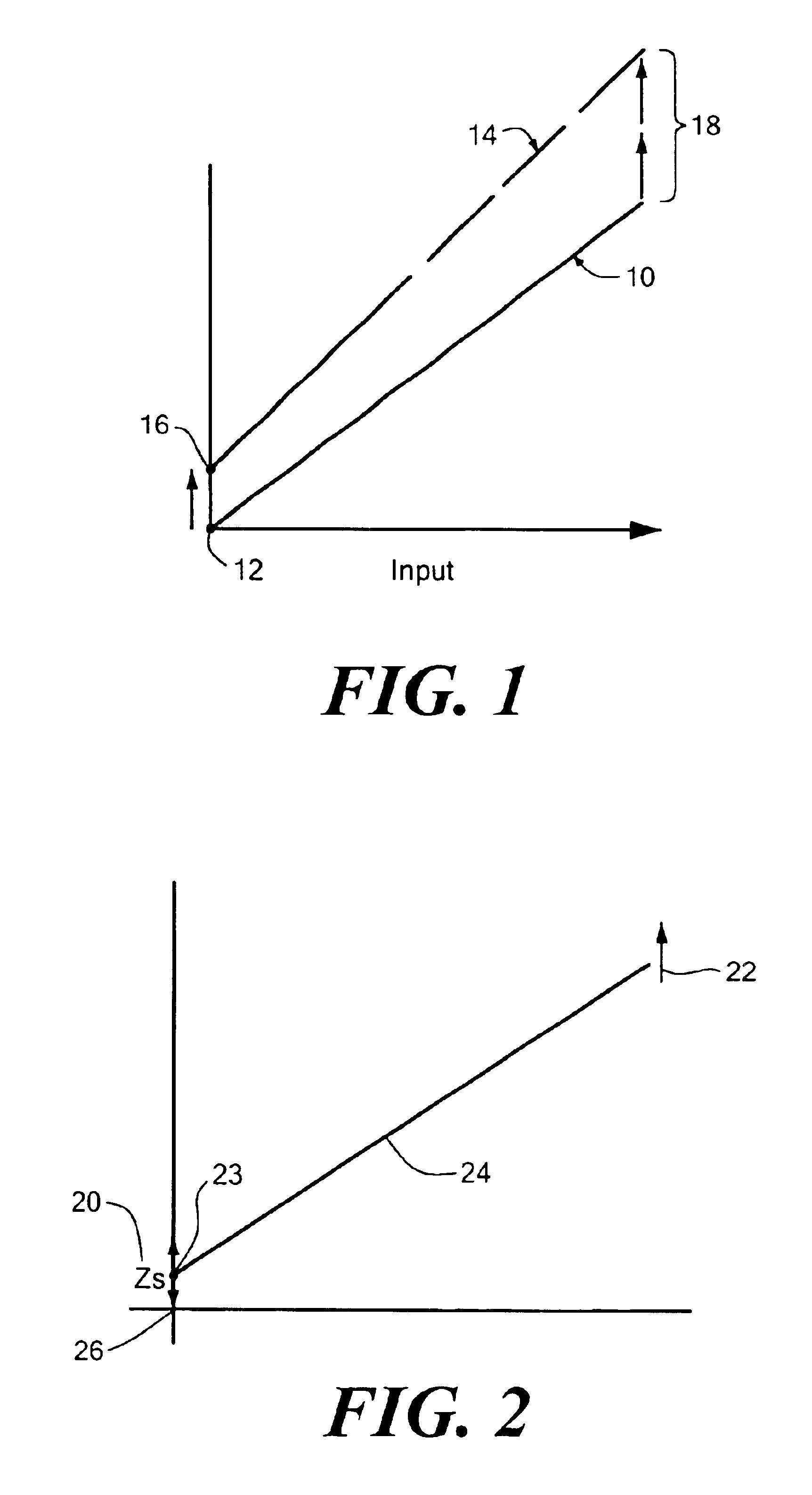
Digital to analog converter (DAC) transfer function end point errors e.g. zero scale and full scale errors; offset and gain errors have historically been a problem effecting (DAC) accuracy.
Previous attempts to reduce such errors have included laser trimming which applied to resistors only and required special hardware and wafer fabrication techniques and added significantly to the cost.
Mixed signal (analog / digital) calibration is another approach but its results can be risky, performance is limiting and less dependable.
It too increases expense.
But the higher the accuracy desired the greater the expense: more precision design and production required, added software and / or circuitry and more expensive fabrication techniques.
In addition, compensating for such errors in systems including the DACs, and their preceding reference path plus subsequent analog chain of circuits (i.e. analog signal chain) requires even greater complexity and expense either in additional and highly accurate integrated circuitry or calibrating system(s) procedures integrated into the system software.

Method used


Image

  • Integrated digital calibration circuit and digital to analog converter (DAC)
  • Integrated digital calibration circuit and digital to analog converter (DAC)
  • Integrated digital calibration circuit and digital to analog converter (DAC)

Examples


example 1

Calculates m and c Coefficients to Correct Gain and Offset Errors

[0067]Vref+=4.096v[0068]Vref−=0v[0069]DAC resolution, N=12[0070]Therefore, ideal LSB=4.096-02n=1⁢mv[0071]Step 100=>102=>Voutzs=−10 mv[0072]Step 100×106=>Voutfs=4.115v[0073]New Step: Calculate⁢ ⁢LSB⁢ ⁢size=Voutfs-Voutzs2n-1=4.115-0.014095=1.002442⁢mvCalculate⁢ ⁢c / z⁢ ⁢s=-(Voutzc-Voutzcideal)LSB⁢ ⁢size=-(-0.01-0)LSB⁢ ⁢size=9.9756[0074]Quantize c / zs to required resolution (12b)=>10Calculate⁢ ⁢m=Ideal⁢ ⁢Output⁢ ⁢RangeVoutfs-Voutzs=4.0954.115-0.010=0.997564[0075]Quantize m to required level (12b)=>4086

example 2

Calculating zs and fs Coefficients to Cancel Zero Scale and Full Scale Errors

[0076]We can extend example No. 1 and use the same data to calculate new coefficients as follows: Set⁢ ⁢dfs=-(Voutfs-Voutfs⁢-⁢ideal)LSB⁢ ⁢size=-(4.115⁢ ⁢v-4.096)1.002442⁢ ⁢mv=18.954=18.954⁢ ⁢LSBs[0077]Quantizing dfs to 12b (LSB) level: dfs→19 LSBs Set⁢ ⁢dfs=VoutfsLSB⁢ ⁢size=4.1151.002442⁢ ⁢mv=4104.97565[0078]Quantizing fs to 12b (LSB) level: fs→4105


PUM


Abstract

An integrated digital calibration circuit and digital to analog converter includes a digital to analog converter (DAC) and a digital calibration circuit including a memory for storing predetermined end point coefficients of the digital to analog converter transfer function; and an arithmetic logic unit for applying the end point coefficients to the DAC input signal to adjust the end points of the DAC and / or analog signal chain.

Description

RELATED APPLICATIONS[0001]This application claims priority of U.S. Provisional Ser. No. 60 / 413,909, Dempsey et at entitled DIGITAL-TO-ANALOG CONVERTER SYSTEM CALIBRATION, filed Sep. 26, 2002; and U.S. Provisional Ser. No. 60 / 414,166, Dempsey et al. entitled DIGITAL-TO-ANALOG CONVERTER CALIBRATION ARCHITECTURE & SCHEME, filed Sep. 27, 2002.FIELD OF THE INVENTION[0002]This invention relates to an integrated digital calibration circuit and digital to analog converter (DAC) for adjusting, modifying, modulating or correcting DAC transfer function end points.BACKGROUND OF THE INVENTION[0003]Adjustment and control of DAC end points e.g. zero scale, full scale or gain and offset is desirable in a number of circumstances. One of the more important uses is end point error correction. That is correction of zero scale and full scale errors and gain and offset errors.[0004]Digital to analog converter (DAC) transfer function end point errors e.g. zero scale and full scale errors; offset and gain ...

Claims


Application Information

Patent Timeline
Patent Type & Authority Patents(United States)
IPC IPC(8): H03M1/10
CPCH03M1/1028H03M1/66
Inventor DEMPSEY, DENNIS A.O'DWYER, THOMAS G.BRENNAN, OLIVER J.WALSH, ALANVINEREANU, TUDOR
Owner ANALOG DEVICES INC
Learn More