Piezoelectric microactuator for improved tracking control of disk drive read/write heads

a technology of disk drive and micro-actuator, which is applied in the direction of record carrier guidance, record information storage, instruments, etc., can solve the problems of increasing the amount of information that can be stored in the computer magnetic disc drive, near the limit of the technology, and unacceptable tracking errors, etc., and achieves precise control at high frequency

Inactive Publication Date: 2006-06-27
KINETIC CERAMICS LLC
View PDF9 Cites 45 Cited by
  • Summary
  • Abstract
  • Description
  • Claims
  • Application Information

AI Technical Summary

Benefits of technology

[0008]The present invention provides a disc drive actuation system for precisely positioning a read / write head over a selected track of a rotatable disc. The actuation system comprises a flexure, a slider, and a read / write head firmly attached to the slider. A first drive unit is used to pivot the flexure to position the read / write head approximately over a selected track. A microactuator is mounted to the flexure and the slider is mounted to the microactuator. The microactuator comprises an inner inactive region, a first outer inactive region, a second outer inactive region, a first piezoelectric section mounted between the first outer inactive region and the inner inactive region, and a second piezoelectric section mounted between the second outer inactive region and the inner inactive region. The inner inactive region is firmly attached to either the flexure or the slider and both of the outer inactive regions are firmly attached to the other of the flexure or the slider. Also, there is an electrical circuit for energizing the first and the second piezoelectric sections to cause them to expand and contract in order to precisely position the read / write head over the selected track. The circuit and the piezoelectric sections are configured such that the first piezoelectric section expands when the second piezoelectric section contracts and the first piezoelectric section contracts when the second piezoelectric section expands. Since the microactuator has to only overcome the inertial mass of the slider and a portion of its own inertial mass, very precise control at high frequency is possible.

Problems solved by technology

As technology has progressed, a major challenge to computer manufacturers has been to increase the amount of information that can be stored in a computer magnetic disc drive.
Increased track density, vibrations in the actuation arm, and vibrations in the suspension of the rotating magnetic disc can cause unacceptable tracking errors.
Voice coil actuation is near the limit of the technology.
However, because the piezoelectric actuators are located at some distance away from the read / write head, vibrations in the actuator arm are added to the piezoelectric actuator output causing read / write head motion that cannot be adequately controlled.
Additionally, high frequency corrections that may be necessary to eliminate the tracking errors cause by bearing vibrations of the rotating disc are not effective when these frequencies approach the resonant frequency of the arm.
However, in the Boutaghou device, there is undesirable friction between the load beam and the slider that impedes the movement of the slider relative to the load beam when the microactuator moves the slider relative to the load beam.

Method used


Image

  • Piezoelectric microactuator for improved tracking control of disk drive read/write heads
  • Piezoelectric microactuator for improved tracking control of disk drive read/write heads
  • Piezoelectric microactuator for improved tracking control of disk drive read/write heads

Examples


second preferred embodiment

[0029]A second preferred embodiment is shown in FIGS. 15–17 and FIGS. 9–11.

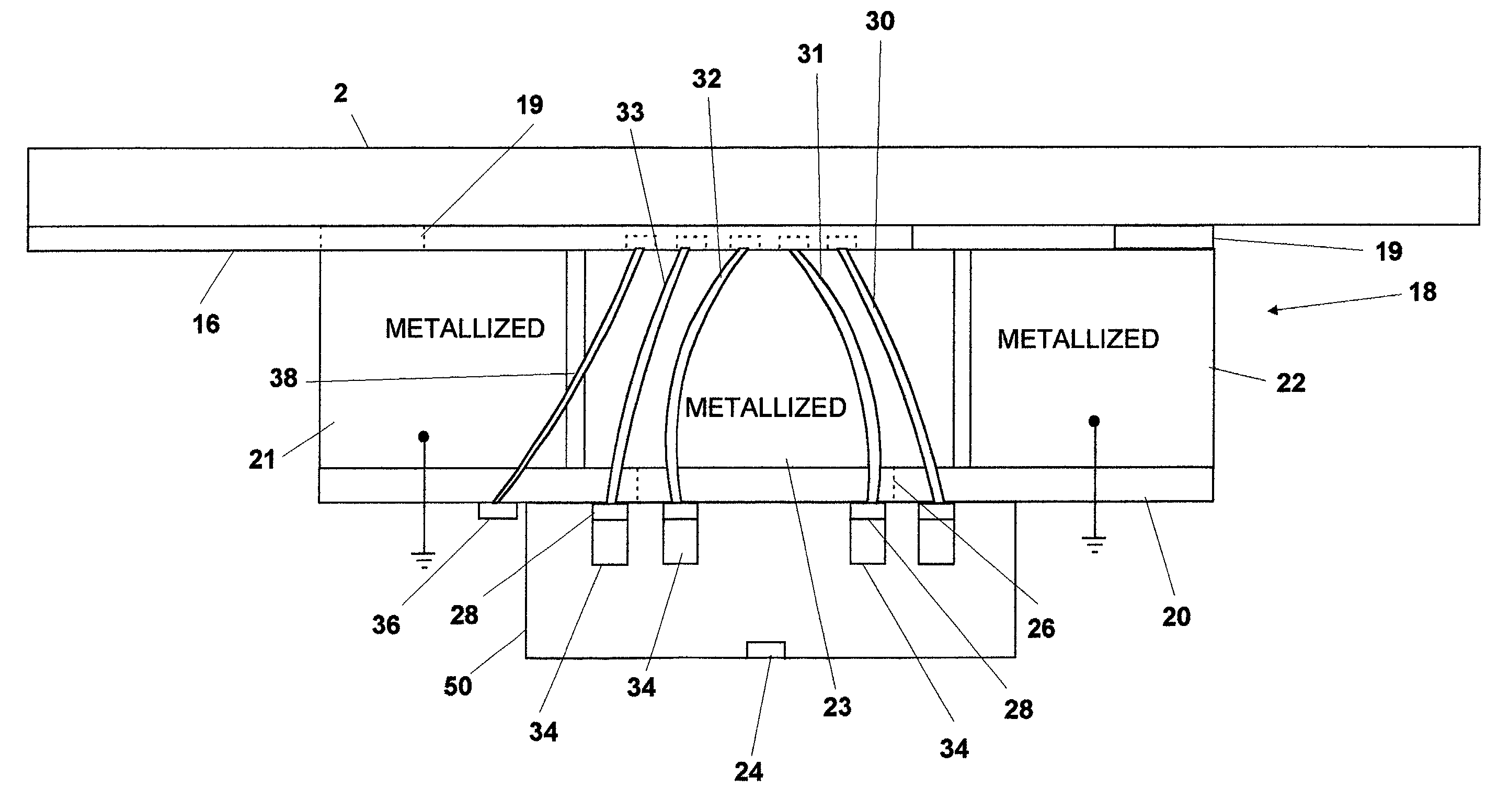
[0030]Microactuator 54 is constructed by first placing piezoelectric layers 58 adjacent to each other as shown in FIG. 15. Metallization layers 64A and 64B are placed between piezoelectric layers 58, as shown. Metallization layers 64A extend cross through the middle of microactuator 54, but do not extend to the end of microactuator 54. In contrast, metallization layers 64B extend to the ends of microactuator 54 but do not cross through its middle. Then, in the preferred embodiment, microactuator 54 is heated to approximately 1100 degrees centigrade in order to firmly bond the different layers of microactuator 18 together.

[0031]As shown in FIG. 16, a metallization coating is then applied to form metallized end sections 55 and 56 and metallized middle section 57. Note that metallization layers 64A contact metallized middle section 57 and metallization layers 64B contact either metallized end section 55 or metal...

third preferred embodiment

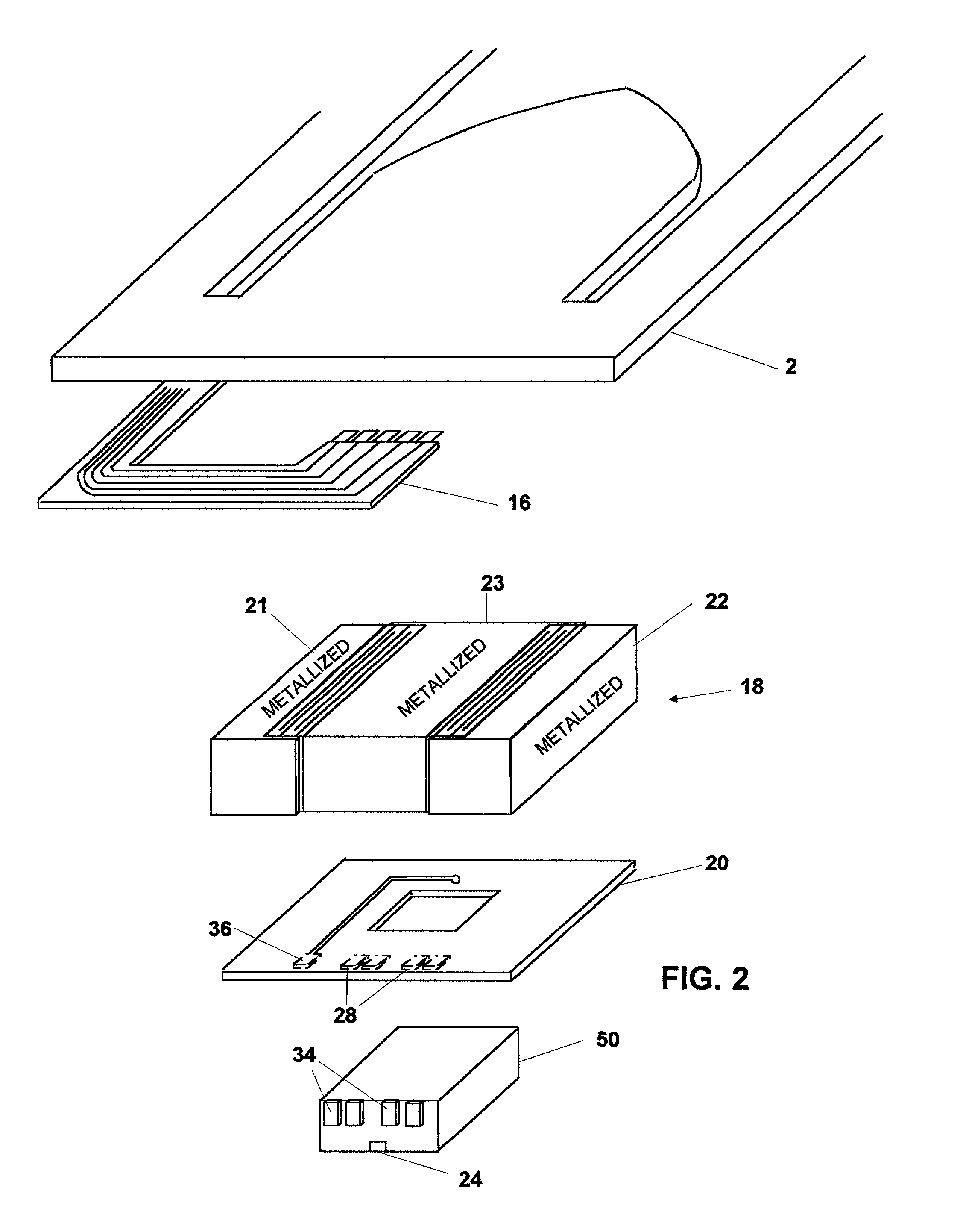
[0035]A third preferred embodiment is shown in FIG. 14. In the third preferred embodiment, metallized middle section 23 is mounted to flexure 2 via adhesive bond 100 and metallized end sections 21 and 22 are mounted to slider 102 via adhesive bonds 104. As with the other embodiments, as piezoelectric section 42 expands piezoelectric section 44 will contract allowing lateral side to side movement of slider 102 without torque or friction being applied to slider 102.


PUM

PropertyMeasurementUnit
aerodynamicaaaaaaaaaa
densityaaaaaaaaaa
frequenciesaaaaaaaaaa

Abstract

A disc drive actuation system for precisely positioning a read/write head over a selected track of a rotatable disc. The actuation system comprises a flexure, a slider, and a read/write head firmly attached to the slider. A first drive unit is used to pivot the flexure to position the read/write head approximately over a selected track. A microactuator is mounted to the flexure and the slider is mounted to the microactuator. The microactuator comprises an inner inactive region, a first outer inactive region, a second outer inactive region, a first piezoelectric section mounted between the first outer inactive region and the inner inactive region, and a second piezoelectric section mounted between the second outer inactive region and the inner inactive region. The inner inactive region is firmly attached to either the flexure or the slider and both of the outer inactive regions are firmly attached to the other of the flexure or the slider. Also, there is an electrical circuit for energizing the first and the second piezoelectric sections to cause them to expand and contract in order to precisely position the read/write head over the selected track. The circuit and the piezoelectric sections are configured such that the first piezoelectric section expands when the second piezoelectric section contracts and the first piezoelectric section contracts when the second piezoelectric section expands. Since the microactuator has to only overcome the inertial mass of the slider and a portion of its own inertial mass, very precise control at high frequency is possible.

Description

[0001]The present invention relates to magnetic disc drive actuation systems, and in particular magnetic disc drive actuation systems that utilize a microactuator.BACKGROUND OF THE INVENTION[0002]As technology has progressed, a major challenge to computer manufacturers has been to increase the amount of information that can be stored in a computer magnetic disc drive. Because data recorded in tracks of a magnetic disc drive must be followed with extreme precision, a disc drive actuation system must be very accurate. FIG. 1A shows a top view of prior art disc drive actuation system 1. Information is stored on concentric tracks 3 of magnetic recording disc 4. Voice coil motor 6 is arranged to rotate actuation arm 8 about pivot axis 10 so as to place read / write head 14 (FIG. 1B) over a track 3. Flexure 2 is suspended from suspended load beam 16. Read / write head 14 is embedded in slider 12 and rides above the surface of disc 4 on an air cushion and is pressed towards disc 4 by suspended...

Claims


Application Information

Patent Timeline
Patent Type & Authority Patents(United States)
IPC IPC(8): G11B21/24G11B5/55
CPCG11B5/5552G11B5/483
Inventor O'NEILL, CONAL
Owner KINETIC CERAMICS LLC
Why Eureka
Try Eureka