
Method for restoring CMOS in a jumperless system

a jumperless system and cmos technology, applied in the field of restoring cmos in a jumperless system, can solve the problems of increasing the probability of an incorrect parameter being present, increasing the complexity of computers, and increasing the number of configuration parameters

Inactive Publication Date: 2006-06-27
HEWLETT PACKARD DEV CO LP
View PDF13 Cites 14 Cited by
  • Summary
  • Abstract
  • Description
  • Claims
  • Application Information

AI Technical Summary

Benefits of technology

The patent describes a method for restoring CMOS parameter values in a computer using a multi-function power switch. By pressing the power button for a specific time delay, the computer can be placed in an off state and then quickly turned on again. This method ensures that the computer can be booted up even if there are changes in the CMOS parameter values during a power-on self test. The technical effect of this method is to provide a reliable and efficient way to restore the computer to its previous state in case of a sudden power loss or other malfunctions.

Problems solved by technology

As the complexity of computers has increased, the number of configuration parameters has increased.
The increased number of parameters has increased the likelihood of an incorrect parameter being present, whether due to faulty user entry or to corruption of the memory contents.
This is of utmost concern since the presence of an error in CMOS may render the computer unbootable, and this error may not be rectified by simply re-booting the computer due to the nonvolatile nature of the CMOS memory.
Without power, the CMOS memory will eventually lose all the stored information.
This time period may be relatively lengthy because stray capacitance in the system may need to completely discharge before the CMOS memory clears.
Most computer users find it undesirable, if not frustrating, to open the computer case, to locate a jumper on the motherboard, to remove and replace the jumper, to close the computer case, and reprogram the BIOS settings.
Further, if the user calls for technical assistance, it is very difficult for a computer support person to guide a novice user through this process over the telephone.

Method used


Image

  • Method for restoring CMOS in a jumperless system
  • Method for restoring CMOS in a jumperless system
  • Method for restoring CMOS in a jumperless system

Examples


Embodiment Construction

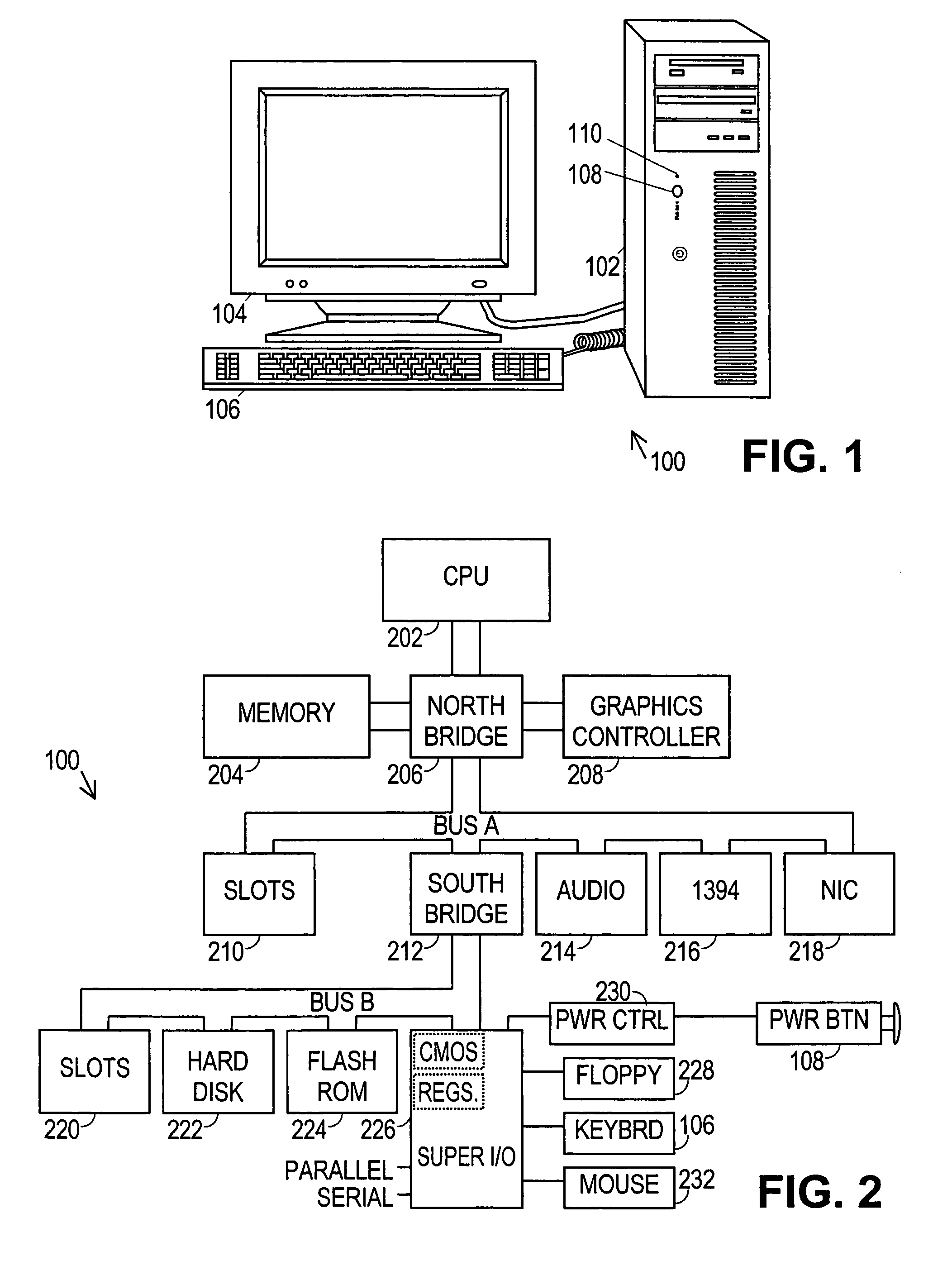
[0020]Turning now to the figures, FIG. 1 shows a computer system 100 in accordance with the preferred embodiment comprising a computer chassis 102 coupled to a display device 104 and a user input device 106. The computer chassis 102 preferably has a power button 108 and may also have a power indicator 110 such as a light emitting diode (“LED”). When the power button 108 is momentarily pressed, power indicator 110 illuminates and computer system 100 boots up. Momentarily pressing power button 108 a second time preferably places the computer system 100 in a reduced-power state.

[0021]At this point, a brief discussion of reduced-power states is warranted. Many computer system manufacturers have implemented a variety of reduced-power states for purposes such as conserving battery power, allowing fast boot-up, providing remote access, and extending component life. A standard known as the Advanced Configuration and Power Management Interface Specification (“ACPI”) has been promulgated by I...


PUM


Abstract

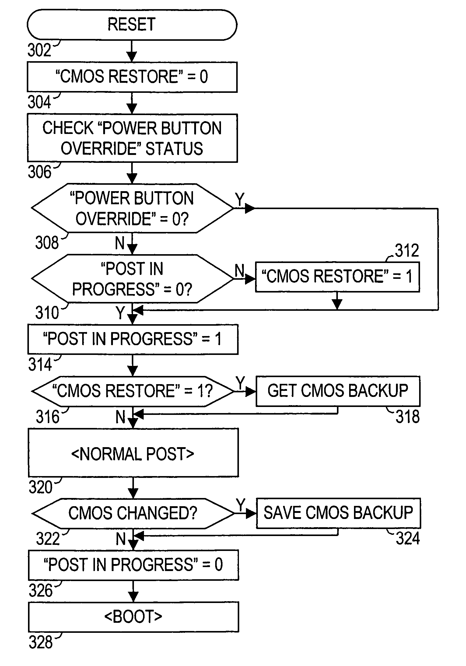
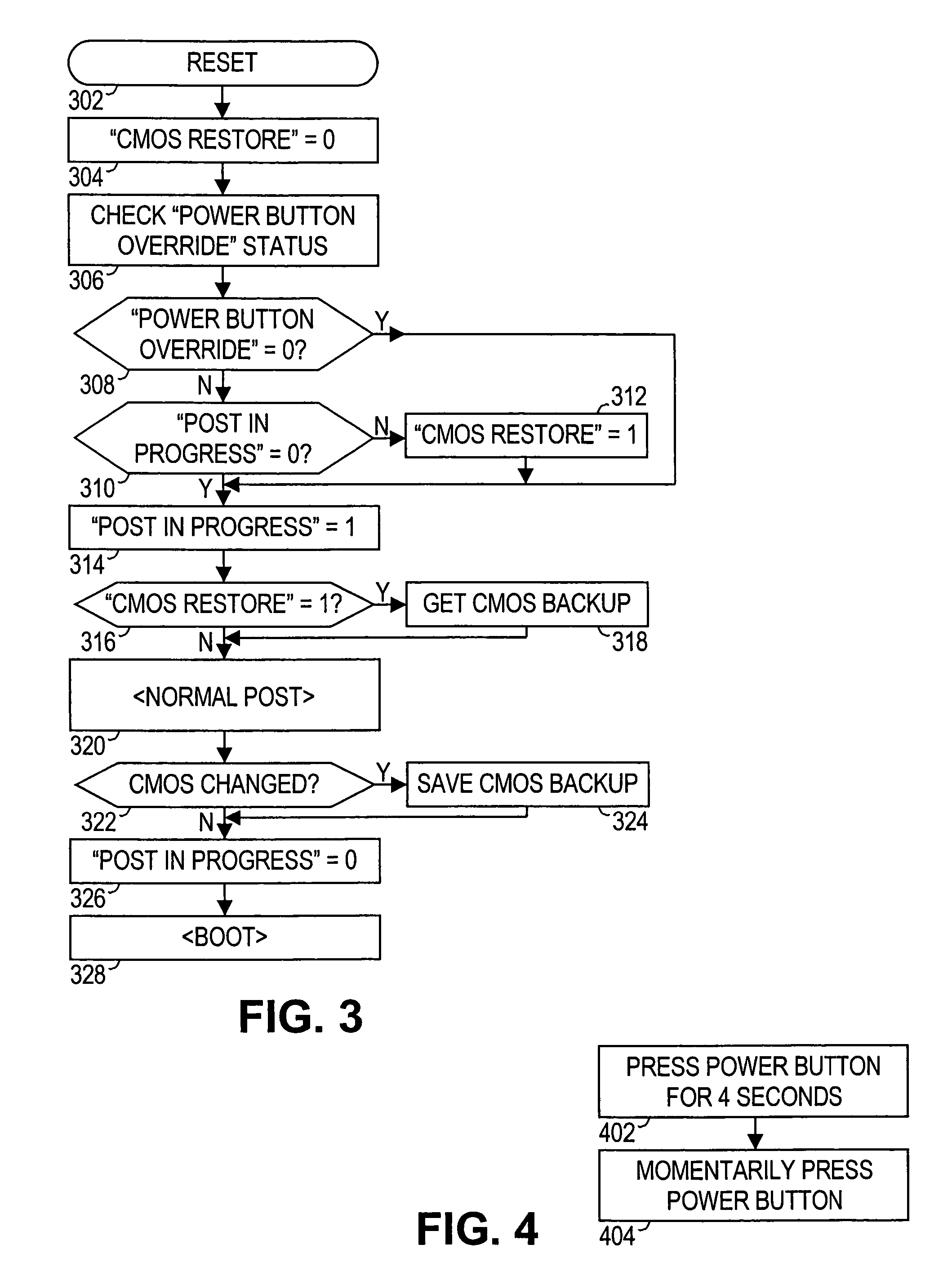
A method for easily restoring CMOS parameters in a computer having a multi-function power button is provided. In one embodiment, the method for restoring CMOS parameter values in a computer includes (a) pressing the power button for a predetermined time delay while the computer is performing a power-on self test (“POST”), thereby placing the computer in an OFF state; and (b) momentarily pressing the power button to turn on the computer. Pressing the power button for four seconds preferably invokes a power button override function. The power button override function unconditionally forces the computer to a “soft-off” state. The BIOS is preferably configured to determine if the power-override function was invoked during the POST in the previous boot-up, and if so, to replace the CMOS parameter values with backup parameter values before proceeding with the current boot-up. The CMOS parameter values are preferably backed up only if they have changed and the BIOS has successfully completed the POST procedure with the changed values. This ensures that the backup values will allow the computer to boot when CMOS parameter restoration is needed.

Description

CROSS-REFERENCE TO RELATED APPLICATIONS[0001]This application is a continuation of U.S. application Ser. No. 09 / 675,354, filed Sep. 29, 2000, now U.S. Pat. No. 6,647,512 and entitled “Method For Restoring CMOS In A Jumperless System.”STATEMENT REGARDING FEDERALLY SPONSORED RESEARCH OR DEVELOPMENT[0002]Not applicable.BACKGROUND OF THE INVENTION[0003]1. Field of the Invention[0004]The present invention relates generally to making computer systems more user-friendly. In particular, the present invention relates to a method for conveniently restoring the default basic input / output system (“BIOS”) parameter settings from a nonvolatile memory in a computer.[0005]2. Description of Related Art[0006]Personal computers include a basic input / output system (“BIOS”) stored in nonvolatile memory. The BIOS is a set of instructions which are executed to conduct the system initialization and to provide control of low level functions in the computer. Normally, the nonvolatile memory is an electricall...

Claims


Application Information

Patent Timeline
Patent Type & Authority Patents(United States)
IPC IPC(8): G06F11/00G06F11/14G06F11/20
CPCG06F11/1417G06F11/1441G06F11/20G06F11/1666
Inventor JAMES, DON R.HESS, RANDALL L.PIWONKA, MARK A.
Owner HEWLETT PACKARD DEV CO LP
Learn More