Partitioning sediment trap

a sediment trap and separation technology, applied in the field of sediment trap separation, can solve the problems of limited sampling accuracy, limited application range, and failure to identify a time-marked interval, and achieve the effects of expanding investigations, simple design of dispensing devices, and small siz

Inactive Publication Date: 2006-07-04
ANDERSON ROGER YATES
View PDF3 Cites 7 Cited by
  • Summary
  • Abstract
  • Description
  • Claims
  • Application Information

AI Technical Summary

Benefits of technology

[0017]Still another advantage of the present invention is the small size and simple design of the dispensing device, as compared to more complex apparatus that employ multiple collecting vessels. Furthermore, the behavior of navicular partitions is independent of size and diameter and is therefore adaptable to a wide range of funnel sizes, collecting tube diameters, ratios of magnification, and conditions of deployment, t...

Problems solved by technology

Although the simple device provided by U.S. Pat. No. 3,715,913 was effective in certain situations, a failure of the marking system to isolate settled materials under some common conditions restricted its use to a limited number of applications.
The problem is traceable to the granules of TEFLON® that were employed to mark time intervals.
A slight and often unavoidable tilting of the collecting tube after deployment resulted in the streaming of granules down one side of the collecting tube, resulting in failure to identify a time-marked interval.
Upon recovery of the collecting tube uncertain boundaries between layers of granules limited the accuracy of sampling.
In addition, granules required removal from a sample before measuring the volume and weight of recovered materials, but other materials were removed also, distorting the measurements of volume and bulk density.
The ab...

Method used


Image

  • Partitioning sediment trap
  • Partitioning sediment trap
  • Partitioning sediment trap

Examples


Embodiment Construction

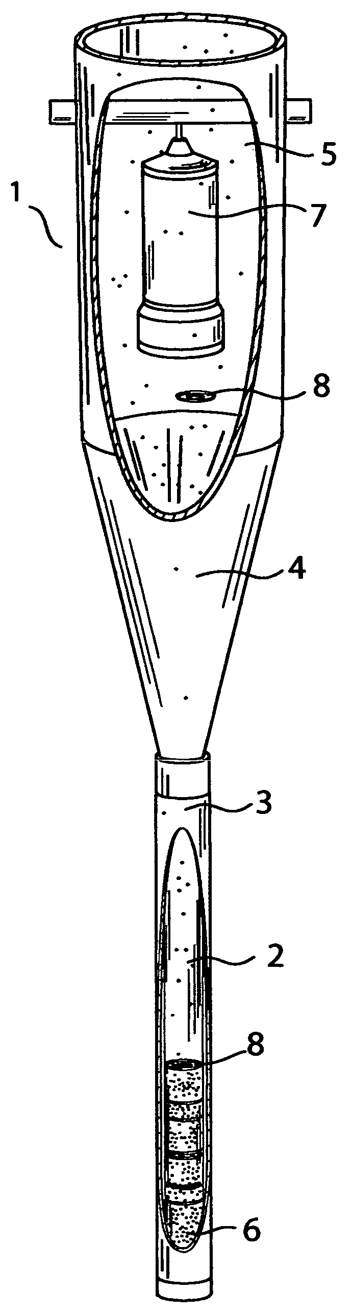
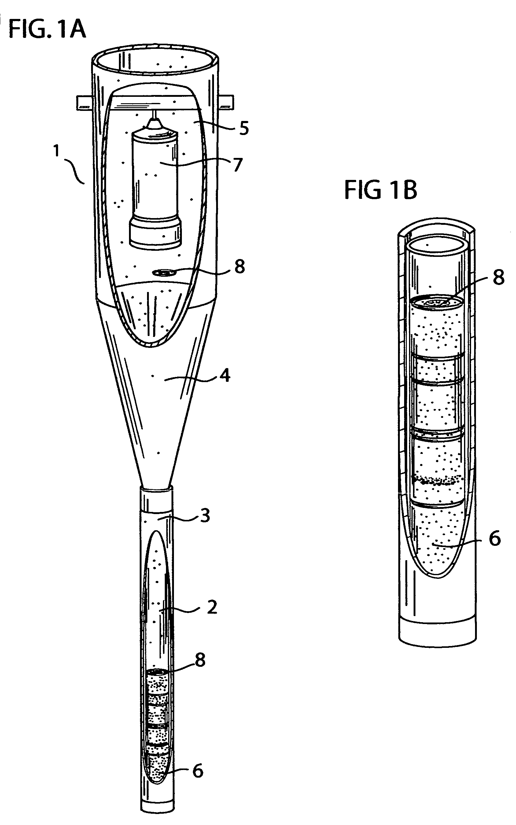
[0024]Referring now to FIGS. 1A and 1B of the drawings, there is shown a partitioning sediment trap, generally designated 1, which has several components in common with the aquatic sediment and pollution monitor described and claimed in my prior U.S. Pat. No. 3,715,913. More specifically, partitioning sediment trap 1 includes a collecting tube 2 having an open upper end and a closed lower end for collecting and storing, over a relatively long period of time, materials, contaminants, and pollutants in a water body. Collecting tube 2 is positioned within a housing tube 3 which is connected adjacent the small diameter end of a cone 4 that magnifies the rate of accumulation of suspended particles 5. The small diameter end of the magnifying cone 4 extends into the collecting tube 2, which is held in position by the housing tube 3. Suspended particles 5 in the water body entering the large diameter opening of the magnifying cone 4 come to rest as settled particles 6 above the lower closed...


PUM


Abstract

A partitioning sediment trap adapted to be positioned in a body of water comprising an elongate, vertically alignable transparent collecting tube having an open upper end and a closed lower end for collecting, over a longer period of time, natural materials, contaminants, and polluting substances that accumulate in the body of water. A generally funnel-shaped cone is positioned with the small diameter end thereof extending into the open end of the collecting tube to magnify the amount of material collected. Means are also provided for automatically and efficiently partitioning and isolating undisturbed material accumulated in the collecting tube at regular time intervals.

Description

CROSS-REFERENCE TO RELATED APPLICATIONS[0001]The above titled application is a significant improvement upon prior patents U.S. Pat. No. 3,715,913 (Aquatic Sediment and Pollution Monitor), and U.S. Pat. No. 4,321,823 (Aquatic Sediment and Current Monitor) previously issued to the above applicant. The above titled application is not related to or referenced to any other prior or pending applications.FEDERAL SPONSORSHIP[0002]Not Applicable.SEQUENCE LISTING OR PROGRAM[0003]Not ApplicableBACKGROUND OF INVENTION[0004]1. Field of Invention[0005]The present invention relates to the collection and measurement of natural materials, contaminants, and polluting substances that accumulate in aquatic environments such as lakes, reservoirs, oceans, estuaries, and other bodies of water, and, more particularly, to apparatus positioned within bodies of water to automatically collect such materials and substances for the purpose of determining composition, rates of movement, and the general condition ...

Claims


Application Information

Patent Timeline
IPC IPC(8): G01N15/04
CPCG01N15/04
Inventor ANDERSON, ROGER YATES
Owner ANDERSON ROGER YATES
Why Eureka
Try Eureka