

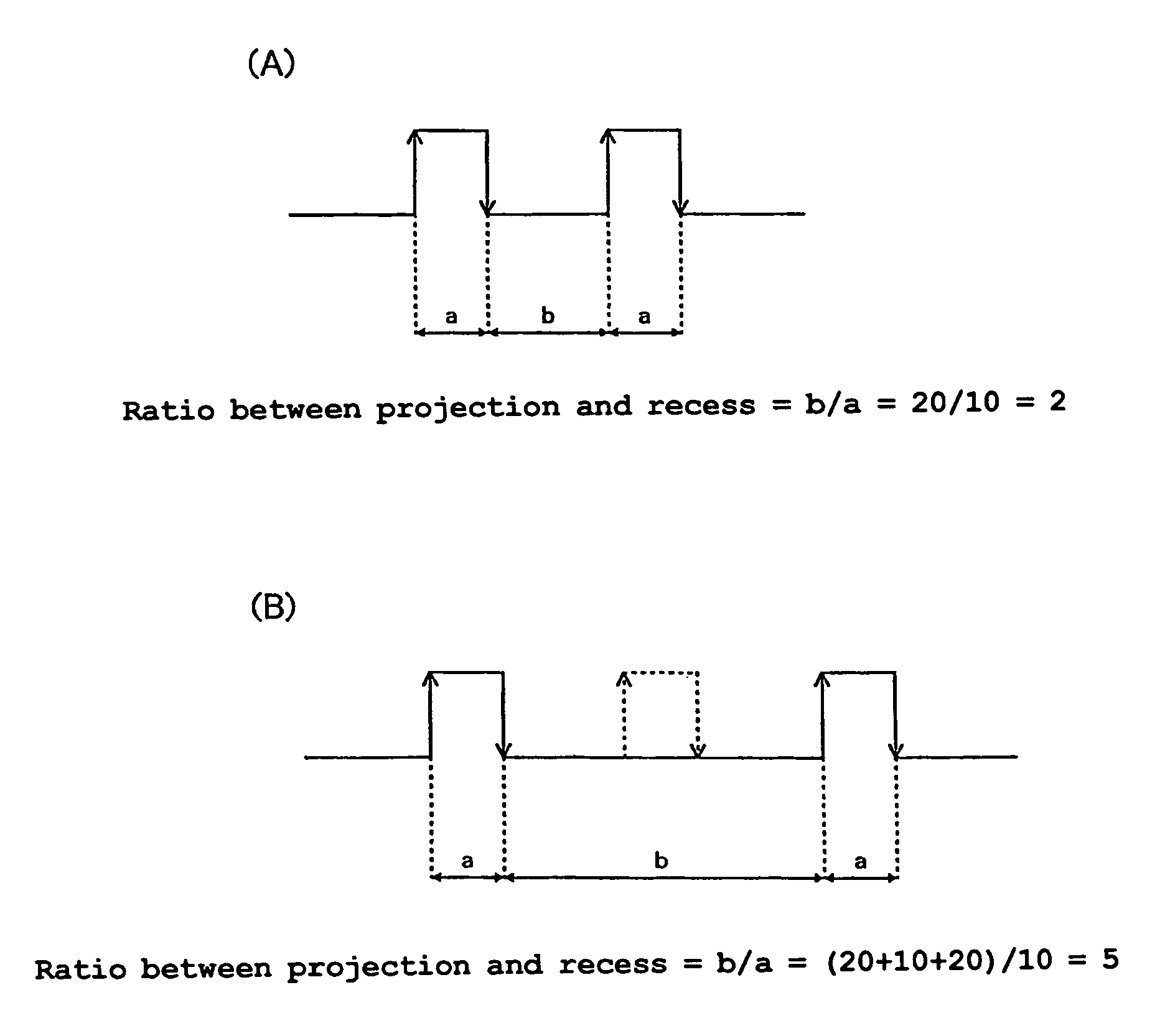
Engine crank angle detecting device
- Summary
- Abstract
- Description
- Claims
- Application Information
AI Technical Summary
Benefits of technology
Problems solved by technology
Method used
Image

Examples
Embodiment Construction
[0021]An embodiment of the present invention will be described below with reference to the accompanying drawings.
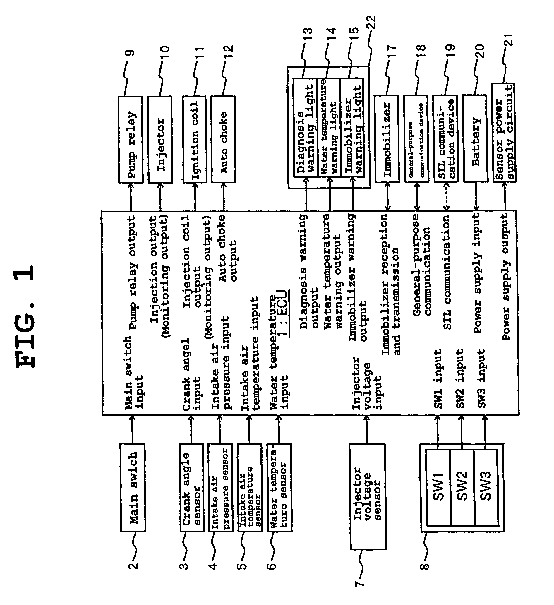
[0022]FIG. 1 is a block diagram of an entire control system of a motorcycle according to the embodiment of the present invention.
[0023]An engine control unit (ECU) 1 is unitized to be an integral component. A control circuit CPU (not shown) of the ECU 1 receives inputs including an on / off signal from a main switch 2, a crank pulse signal from a crank angle sensor 3, an intake air pressure detection signal from an intake air pressure sensor 4, an intake air temperature detection signal from an intake air temperature sensor 5, a cooling water temperature detection signal from a water temperature sensor 6, a voltage signal from an injector voltage sensor 7 for controlling an injector, and a checking input signal from a switch box 8 having a plurality of switches SW1 to SW3. The ECU 1 is also connected to a battery 20, from which battery power supply is inputted.
[0024]For out...
PUM
 Abstract
Description
Claims
Application Information