Vehicular mirror system with at least one of power-fold and power-extend functionality

a technology of power-folding and power-extending, which is applied in the direction of mirrors, mountings, instruments, etc., can solve the problems of premature motor failure, premature failure of associated electrical circuitry, premature motor failure, etc., and achieve the effect of increasing the drive force and reducing the drive for

Inactive Publication Date: 2006-07-04
MAGNA MIRRORS OF AMERICA INC
View PDF22 Cites 36 Cited by
  • Summary
  • Abstract
  • Description
  • Claims
  • Application Information

AI Technical Summary

Benefits of technology

[0020]The first linkage can comprise a rack gear operably connected to a spur gear, and the spur gear can be prevented from movement relative to the fixed portion during the first stage. The fixed portion can include a first conductor located along a pivotal movement region; the moveable portion can include a second conductor maintained in operable interaction with the first conductor in the pivotal movement region along the normal range of movement; and the actuator can have at least one terminal operably interconnected to the second conductor. Operable interconnection is thereby maintained between the actuator and the first conductor during pivotal movement of the moveable portion relative to the fixed portion throughout at least the normal range of movement thereof.
[0024]In another aspect of the invention, an external mirror system for a vehicle comprises: a fixed portion adapted to be mounted to the vehicle; a moveable portion pivotally mounted to the fixed portion through a normal range of movement between a folded position and an unfolded position defined by a pair of terminal ends, the moveable portion having a reflective element mounted therein; an actuator having a non-rotatable portion mounted to the fixed portion and a rotatable portion mounted to the movable portion, wherein relative rotation of the rotatable portion of the actuator with respect to the non-rotatable portion causes the movable portion to be pivoted with respect to the fixed portion; and a force-modifying device operably interconnected to the actuator for reducing a drive force required to pivot the movable portion relative to the fixed portion within the normal range of movement corresponding to the folded and unfolded positions and increasing the drive force required to pivot the movable portion relative to the fixed portion beyond one of the terminal ends of the normal range of movement.

Problems solved by technology

The action of continuing the operation of the motor even after the mirror limit of movement has been reached means that the motor may be forced to work against a virtually immovable obstacle in the form of the stops.
In such a case, the current load through the motor will typically increase significantly above the normal operating current, leading to overheating and, eventually, premature motor failure.
The increased current load can also lead to overloading and premature failure of associated electrical circuitry, such as the controller, or stripping or other mechanical failure of gears and other mechanical components.
Any of these failures will require difficult and costly replacement of the failed parts.
Increasing the friction between the rotatable column and the mirror bracket, while providing a more desirable holding force, requires a more heavy-duty motor to drive the rotatable column, thus increasing cost.
Nevertheless, the repeated flexing of the wiring harness can lead to breakage of individual wires and failure of one or more of the power functions, necessitating costly replacements.
Furthermore, the greater the number of power functions, the larger and heavier the wiring harness required, which can add significant weight to the mirror assembly.
Finally, fabrication and routing of the wire harness through the mirror assembly can be complicated, requiring additional steps in the manufacture of the mirror assembly, with consequent additional cost.
The use of separate motors for each function is not desirable because it increases costs and part count, which are undesirable characteristics in the automotive parts supply industry.
The extra motor also increases the volume of the mirror housing, which is also typically undesirable since increased volume can lead to increased drag, which negatively impacts fuel mileage, and increased wind-induced noise.
The costs and labor of maintaining multiple designs and assembling different features into a vehicle mirror are often burdensome.
If the power is not cut off, the motor can overheat and become damaged.
Current attempts to solve this problem have typically fallen short of a desirable solution.
However, it has been found that this motor control circuit is temperature-sensitive, causing undesirable results when the circuit is used through a wide range of ambient temperatures.
It has also been found that a resetable fuse can be provided in series with the motor, however, this arrangement can provide an undesirable recovery time (i.e., waiting for the fuse to reset).
This can create a potential “blind spot” as shown by the shaded region in FIG. 113 which could cause the driver 1318 to not be able to see adjacent vehicles, creating a dangerous driving condition.

Method used


Image

  • Vehicular mirror system with at least one of power-fold and power-extend functionality
  • Vehicular mirror system with at least one of power-fold and power-extend functionality
  • Vehicular mirror system with at least one of power-fold and power-extend functionality

Examples


first embodiment

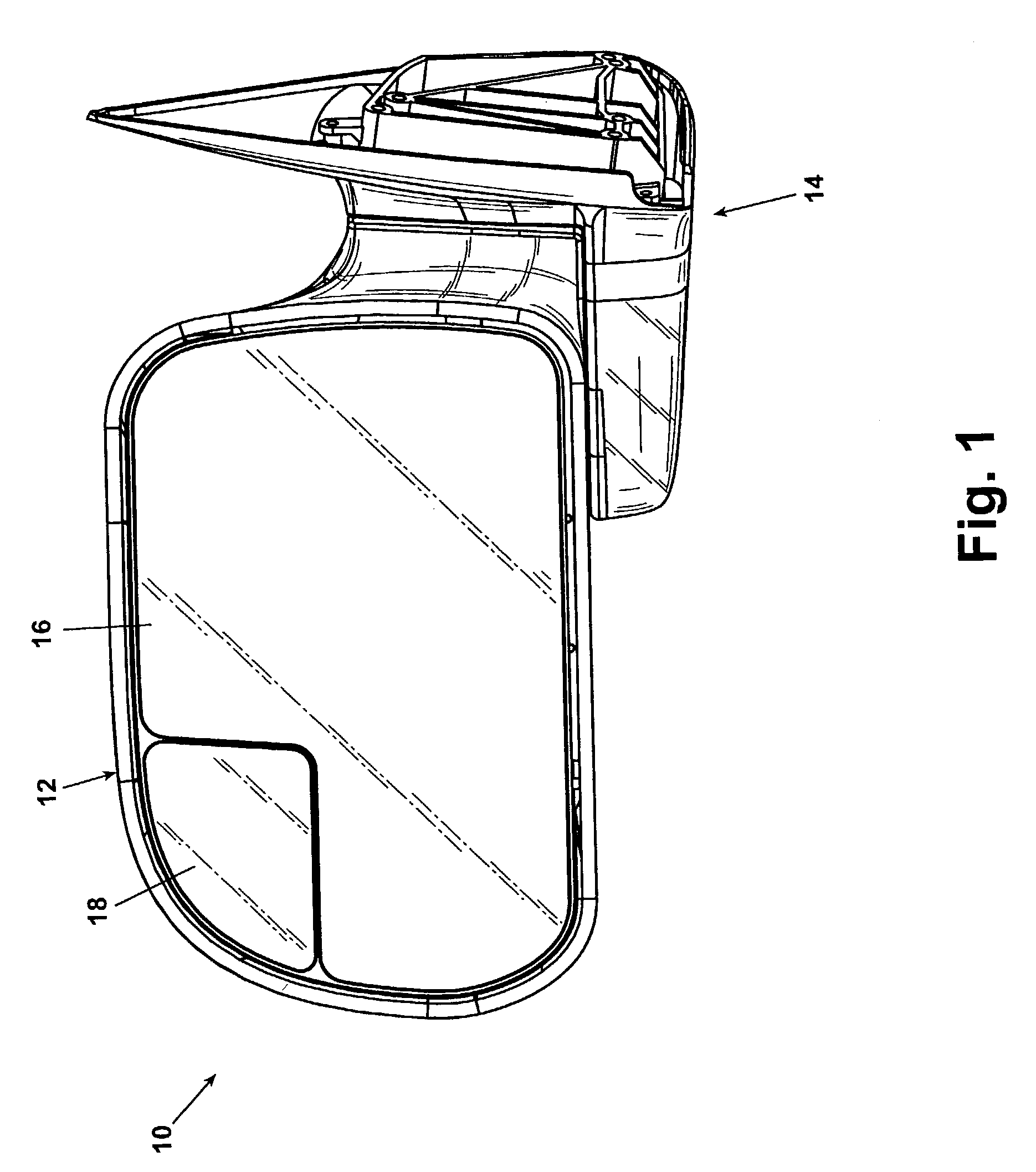
[0198]Referring now to the drawings and to FIGS. 1–4 in particular, a vehicular mirror assembly 10 is shown comprising a mirror housing 12 pivotally and extendably mounted to a base 14, and driven by a motive element such as a 12-volt DC motor. The mirror housing 12 preferably carries a reflective element, such as a mirror, as identified by reference number 16. It will be understood that alternative and additional accessories for the mirror housing 12, base 14, and reflective element 16 can be included without departing from the scope of this invention. For example, the reflective element 16 can also include a wide view portion 18 as would be known to one skilled in the art. Other optional accessories include illumination devices such as a turn signal, or an assist light, and the like.

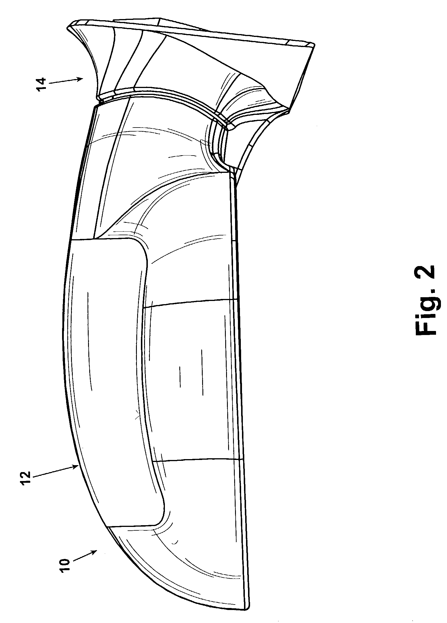
[0199]FIGS. 1 and 2 show the vehicular mirror assembly 10 located in an unfolded, use position wherein the mirror housing 12 is pivoted radially outwardly from the base 14 (i.e., adjacent the vehicle) ...

third embodiment

[0233]FIG. 21 illustrates the pivot mechanism 120. The pivot mechanism 120 is preferably fixedly mounted within the base 14 and includes a rotatable column hereinafter described which is mounted to the mirror housing 12 to effect the pivotal movement of the mirror housing 12 relative to the base 14.

[0234]The pivot mechanism 120 comprises an outer housing 122 and a base 370 which enclose a ramp 150, a wave spring 170, an actuator sub 180, a motor housing 260, a motor 300, and gear assemblies 310, 360. Referring also to FIGS. 22 and 23, the outer housing 122 is a generally cylindrically-shaped body comprising a cylindrical wall 124 and a collar 126 connected to the cylindrical wall 124 by an annular wall 128 and coaxial therewith. The annular wall 124 extends orthogonally inwardly from the cylindrical wall 124 to the collar 126. Referring to FIG. 23, the inner surface of the annular wall 128 is provided with a pair of diametrically-opposed inner bosses 142 extending downwardly from th...

fourth embodiment

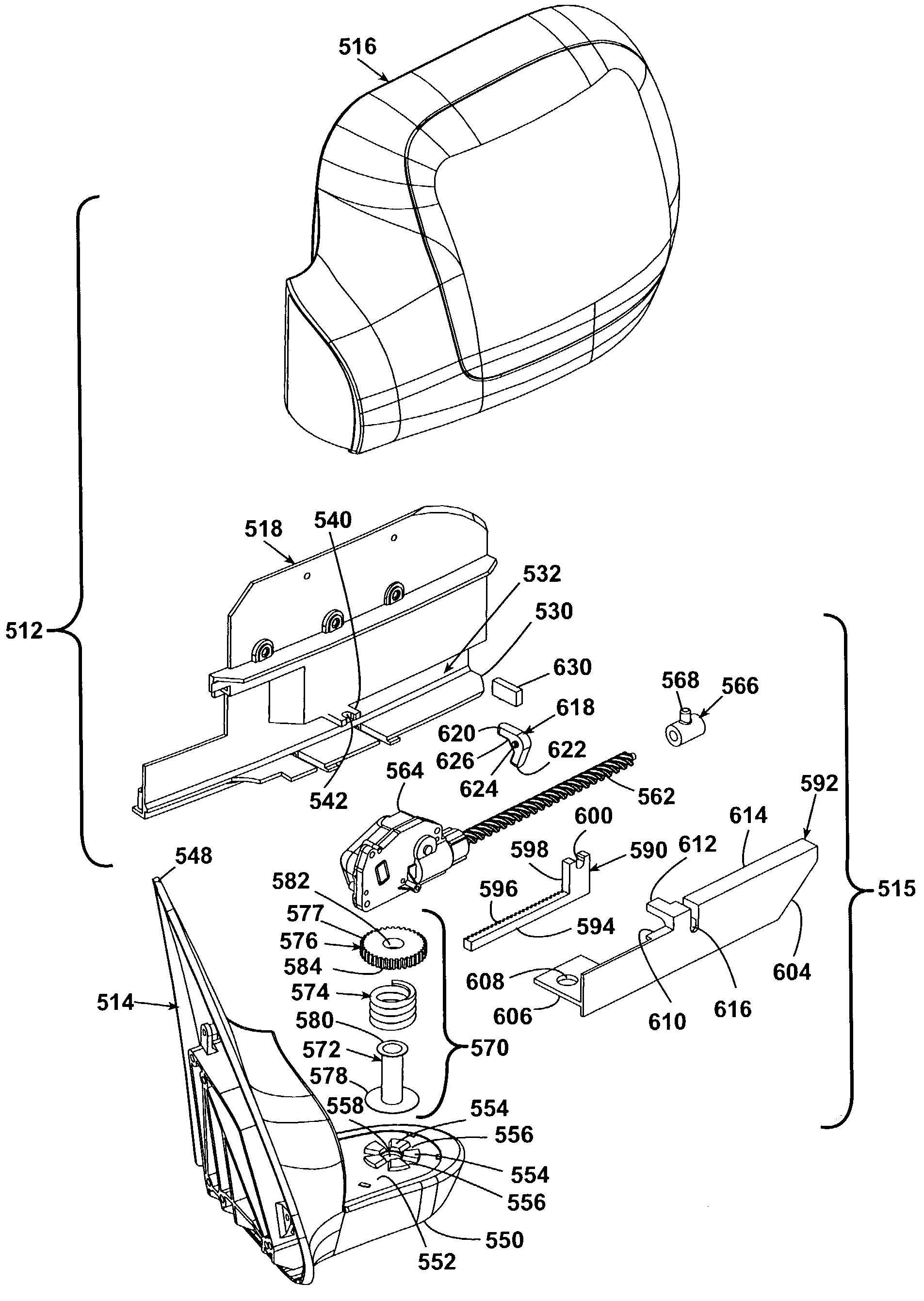
[0261]FIG. 41 illustrates a vehicle mirror 510 having both a power fold and a power extend function according to the invention. The vehicle mirror 510 comprises a mirror assembly 512 and is mounted to a vehicle by a support bracket or arm 514. Referring to FIG. 42, the mirror assembly 512 is connected to the support arm 514 by a drive assembly or transmission 515, which is used to rotate the mirror assembly between folded and unfolded positions and extend the mirror assembly between retracted and extended positions.

[0262]Referring to FIGS. 41–44, the mirror assembly 512 comprises a mirror housing 516 in which is received a mirror bracket 518 that supports a mirror drive 520 for adjusting the position of the mirror 522 mounted to the mirror drive 520. The mirror drive 520 and mirror 522 are well known and will not be described in further detail.

[0263]Referring specifically to FIG. 43, the mirror bracket 518 comprises a generally planar upper face 528 on which the mirror drive 520 is ...


PUM


Abstract

A motorized pivoting and extending mechanism for a vehicular mirror assembly includes, alternatively, a force-reduction mechanism for reducing the friction within the mechanism, and a slip clutch mechanism for reducing overloading of the motor when the limits of mirror extension and retraction have been reached. Mirror power functions receive electrical power and control signals through a circular array of electrical contacts incorporated into the pivot connection irrespective of the pivotal orientation of the mirror. A motor shut-off circuit is able to shut off the motor within a predetermined period of time. The mirror can be angularly adjusted upon movement of the mirror between the retracted and the extended positions to maintain a common field of view for a driver of the vehicle to prevent the extension and / or retraction of the mirror from undesirably repositioning the field of view captured by the mirror.

Description

CROSS-REFERENCE TO RELATED APPLICATION[0001]This application claims the benefit of U.S. provisional applications Ser. Nos. 60 / 319,198, filed Apr. 23, 2002; 60 / 319,243, filed May 14, 2002; 60 / 319,244, filed May 14, 2002; 60 / 319,324, filed Jun. 18, 2002; 60 / 319,394, filed Jul. 12, 2002; 60 / 319,412, filed Jul. 19, 2002; 60 / 319,508, filed Aug. 29, 2002; 60 / 319,637, filed Oct. 21, 2002; and 60 / 319,821, filed Dec. 30, 2002, which are incorporated herein in their entirety.BACKGROUND OF THE INVENTION[0002]1. Field of the Invention[0003]In one of its aspects, the invention relates to a vehicular mirror assembly adapted to be mounted to a vehicle for movement between an extended and a retracted position. More particularly, the invention relates to a pivoting mechanism for performing the pivotal movement of the vehicular mirror assembly including a mechanism for reducing the friction within the pivoting mechanism. In another aspect, the invention relates to an external vehicle mirror having bo...

Claims


Application Information

Patent Timeline
Patent Type & Authority Patents(United States)
IPC IPC(8): G02B5/08B60R1/074B60R1/078
CPCB60R1/078B60R1/074
Inventor FOOTE, KEITH D.BROWN, KRIS D.PETERSON, KENNETH C.RUSE, JAMES A.
Owner MAGNA MIRRORS OF AMERICA INC
Why Eureka
Try Eureka