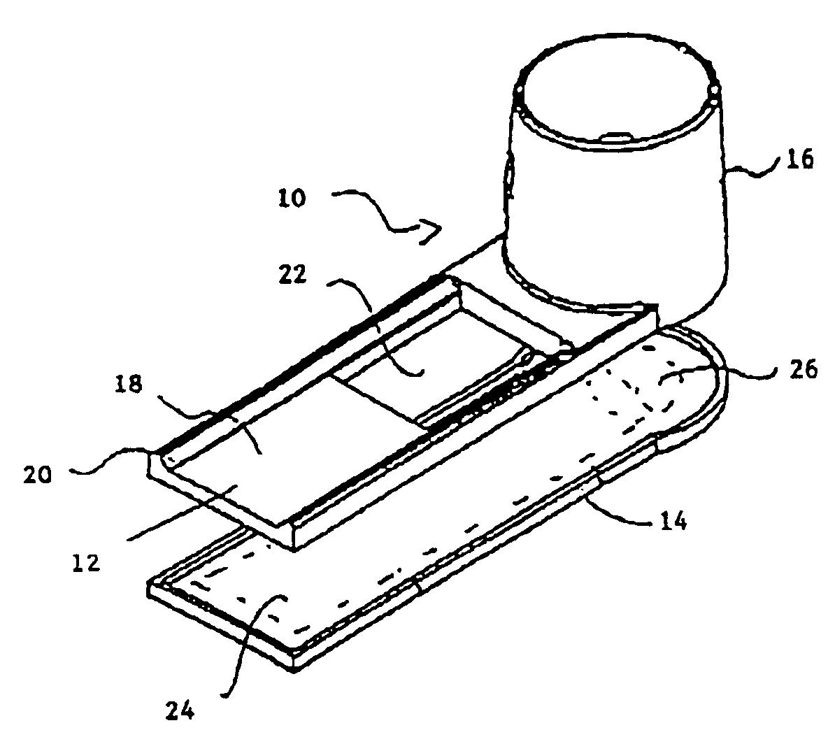
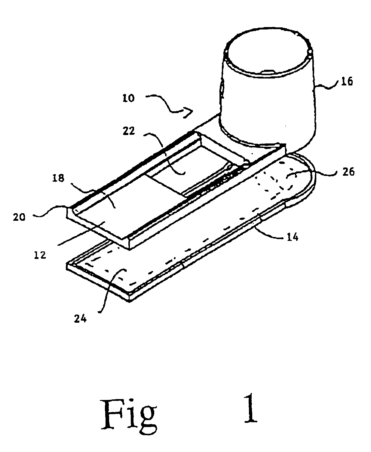
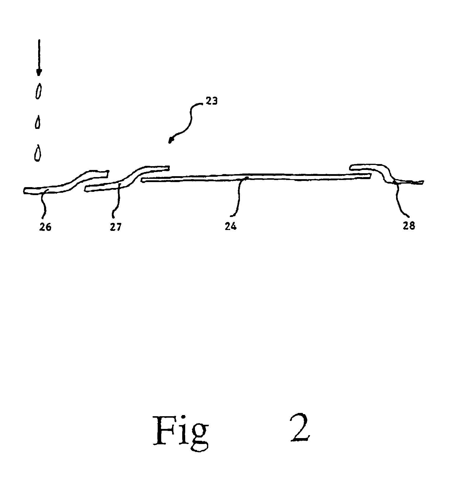
Screening arrangment for screening immunoassay tests and agglutination tests

a screening device and immunoassay technology, applied in the field of screening devices and methods of screening immunoassay tests and agglutination tests, can solve the problems of high operator difficulty in eye detection of cannabis levels of 6 ng/ml or lower, and the operator is more likely to be subject to inaccuracy, so as to achieve the effect of low drug concentration, low drug concentration and low sample siz

Inactive Publication Date: 2006-07-04
COZART BIOSCIENCE LTD
View PDF18 Cites 29 Cited by
  • Summary
  • Abstract
  • Description
  • Claims
  • Application Information

AI Technical Summary

Problems solved by technology

This is difficult, requiring highly trained and skilled operators, and can prove unreliable when the levels of drugs are very low.
For example, it is particularly difficult for an operator to distinguish between levels of cannabis of 6 ng / mL or lower by eye.
If the test is to be run outside the laboratory, it is even more likely to be subject to inaccuracies which may be exacerbated by poor lighting conditions or by other environmental factors.

Method used


Image

  • Screening arrangment for screening immunoassay tests and agglutination tests
  • Screening arrangment for screening immunoassay tests and agglutination tests
  • Screening arrangment for screening immunoassay tests and agglutination tests

Examples


second embodiment

[0103]FIG. 10 shows a cut away side view of a test swab which incorporates both the spike 64 and the run fluid within the test swab, and thus removes the need for these to be provided in the test cartridge.

[0104]The handle 74 of test swab 70 is made from a transparent is outer tube 78 open at the lower end thereof and closed at the top end thereof. At the lower end of the outer tube 78 a flange 76 is provided which protrudes outwardly from the outer tube 78. The flange 76 may extend around the entire periphery of outer tube 78 or may extend only around part or parts of the periphery of outer tube 78. An adequate spike 64 extends from the closed top end of the outer tube 78 downwardly. Alternatively, instead of a spike, a pin or any other sharp protrusion may be used.

[0105]A saliva collection pad 72 is attached to the lower end of tube 79. The tube 79 is open at both ends. The diameter of the bore of the tube 79 is large enough to allow the spike 64 attached to the outer tube 78 to e...

third embodiment

[0107]FIG. 12 shows a cut away side view of a test swab which is suitable for use with a test cartridge. This embodiment of test swab 70 requires that a spike 64 is provided in the swab holder 16 of the test cartridge. As shown in FIG. 14 the spike 64 is attached to a spike holder 65 which in turn is attached to the swab holder 16. The spike 64 preferably has a cruciform cross-section as shown in FIG. 15. The test swab 70 comprises a saliva collection pad 72, a main tube 108, a run fluid chamber, or capsule, 68′ and an indicator section. The indicator section comprises a capillary tube 110, a dye release pad 102 and a dye receptor pad 100. The saliva collection pad 72 is in communication with the open base of a main tube 108. The upper end of the main tube is also open. A penetrable gelatine capsule 68′ filled with run fluid is located within the main tube 108 spaced from the saliva collection pad 72. Disposed to the side of the main tube 108 is a capillary tube 110. A small port 11...


PUM

PropertyMeasurementUnit
weightaaaaaaaaaa
weightaaaaaaaaaa
sizeaaaaaaaaaa

Abstract

A screening device for performing an immunoassay test to detect the presence of a compound in a body fluid. The device includes a holder for removably receiving a membrane to which the fluid has been applied. A light is directed to the membrane. A photodetector measures the concentration of the light reflected back from the membrane. Specifically, the concentrations of reflected light from a control zone and a test zone are measured. Signals representative of the measured light concentrations are applied to a processor. If a specified concentration of predetermined light from a control zone on the membrane is detected, the processor considers the test to be successful. In the test is successful, the processor, based upon the measured concentration of reflected light from the test zone, generates data representative of the presence of the compound.

Description

RELATIONSHIP TO EARLIER FILED APPLICATION[0001]This application is a continuation-in-part of International Application PCT / GB99 / 02261, publication No. WO 00 / 04381, with an International filing date of Jul. 14, 1999.BACKGROUND OF THE INVENTION[0002]This invention relates to a screening device and methods of screening immunoassay tests and agglutination tests. In particular the invention is applicable to a screening device for detecting the presence and concentration of particular drugs in a sample of saliva.[0003]Samples of bodily fluid such as blood, sweat, urine and saliva may be used to detect the presence of particular is compounds, such as drugs, in the body. Known methods of testing such samples for the presence of compounds include immunoassay “strip” testing where an antibody is labelled with a suitable marker, for example a visible marker such as colloidal gold, and drawn along a membrane passing over test regions and a control region impregnated with analyte conjugate subst...

Claims


Application Information

Patent Timeline
Patent Type & Authority Patents(United States)
IPC IPC(8): G01N33/53G01N33/543
CPCG01N33/54366Y10S435/81Y10S436/805Y10S435/805Y10S435/97
Inventor SPIVEY, ROBIN JAMESHAND, CHRISTOPHER WILLIAMBALDWIN, DENEJONES, OSBORN PIERCE
Owner COZART BIOSCIENCE LTD
Why Eureka
Try Eureka