Cooling water circuit system

a circuit system and cooling water technology, applied in the direction of engine cooling apparatus, engine lubrication, control device of cooling apparatus, etc., can solve the problems of deteriorating the warming-up performance of lubricant oil after engine start, insufficient lubricant oil,

Active Publication Date: 2006-07-11
DENSO CORP
View PDF8 Cites 23 Cited by
  • Summary
  • Abstract
  • Description
  • Claims
  • Application Information

AI Technical Summary

Benefits of technology

[0004]In view of the above-described problems, it is an object of the present invention to provide a cooling water circuit system for a vehic...

Problems solved by technology

However, in this heat exchanger, because the lubricant oil is heated by using cooling water (hot water) in a heater water circuit to sufficiently heat the lubricant oil in the warming-up operation, the lubricant oil may be not sufficiently cooled in the ...

Method used


Image

  • Cooling water circuit system
  • Cooling water circuit system
  • Cooling water circuit system

Examples


first embodiment

(First Embodiment)

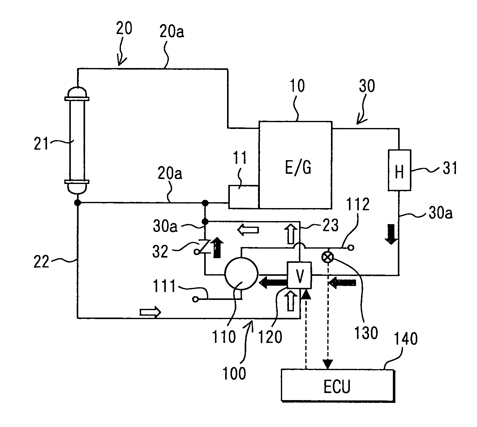
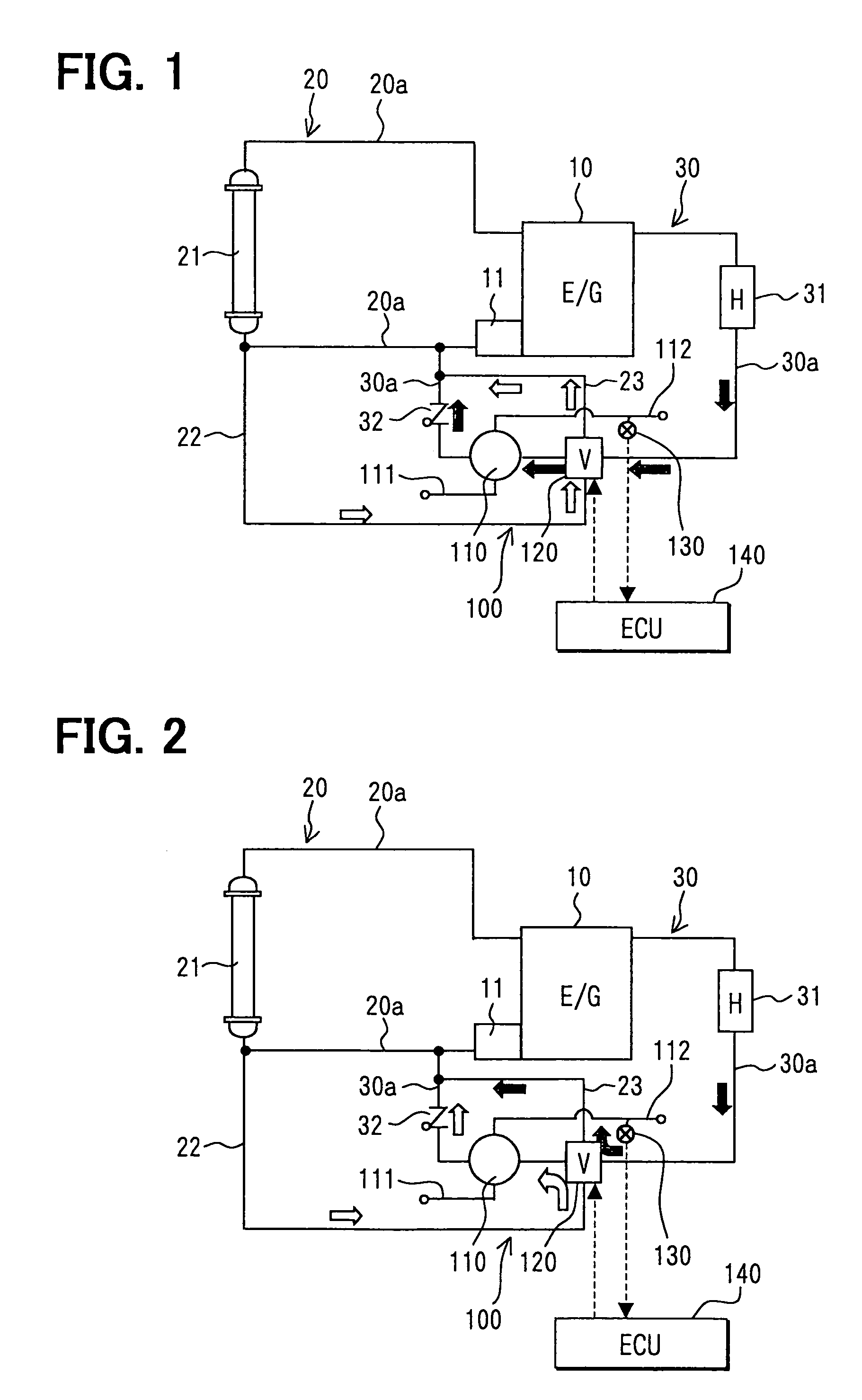
[0017]The first embodiment of the present invention will be now described with reference to FIGS. 1–3. A vehicle engine 10 is provided in a cooling water circuit system in which cooling water (coolant) for cooling the vehicle engine 10 flows. The vehicle engine 10 includes an automatic transmission (not shown) that is provided with a torque converter for operating a clutch and various gears for transmissions. Lubricant oil (ATF) is used in the torque converter as a power transmission medium. A cooling water circuit 100 is provided for rapidly increasing the temperature of the lubricant oil when the temperature of the lubricant oil is lower than a set temperature after an engine start, and for cooling the lubricant oil at a suitable temperature in an engine normal operation.

[0018]The cooling water circuit system of the engine 10 includes a radiator water circuit 20 for adjusting the temperature of the engine 10 at a suitable temperature. The radiator water circuit 2...

second embodiment

(Second Embodiment)

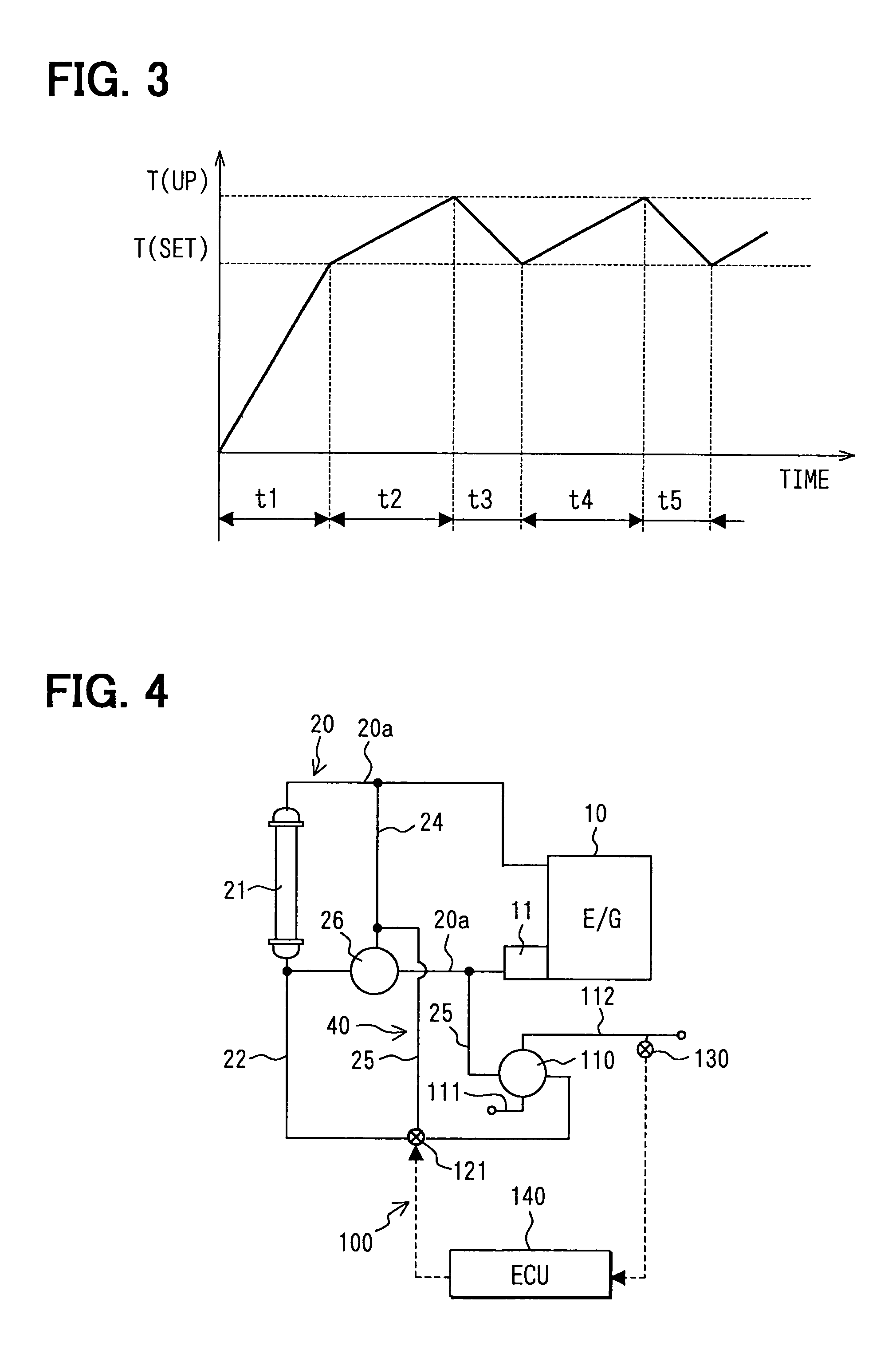
[0035]The second embodiment of the present invention will be now described with reference to FIG. 4. In the second embodiment, a radiator main bypass passage 24, through which cooling water bypasses the radiator 21, is provided in a cooling water circuit system. Furthermore, a thermostat 26 is provided at a join portion where the radiator water passage 20a at a downstream side of the radiator 21 and the radiator main bypass passage 24 are joined.

[0036]A branch passage 25 branched from the radiator main bypass passage 24 is provided. Through the branch passage 25, refrigerant from the radiator main bypass passage 24 returns to the engine 10 after passing through the oil cooler 110. A branch bypass circuit 40 is constructed with the radiator main bypass passage 24 and the branch passage 25, so that refrigerant from the engine 10 returns to the engine 10 through the branch bypass circuit 40 while bypassing the radiator 21. The branch bypass circuit 40 is a radiator b...


PUM


Abstract

A cooling water circuit system for an engine includes a radiator bypass passage through which cooling water of the engine bypasses a radiator, a heat exchanger disposed in the radiator bypass circuit to perform heat exchange between the cooling water and lubricant oil of an automatic transmission, and a radiator downstream passage through which the cooling water from the radiator flows into the heat exchanger. Further, a flow adjusting unit is disposed at a join portion where the radiator bypass passage and the radiator downstream passage are joined, to adjust a flow ratio between the cooling water flowing from the radiator downstream passage to the heat exchanger and the cooling water flowing from the radiator bypass passage to the heat exchanger. The flow adjusting unit is controlled by a control unit in accordance with the temperature detected by the temperature detection unit.

Description

CROSS REFERENCE TO RELATED APPLICATION[0001]This application is based on Japanese Patent Application No. 2003-348679 filed on Oct. 7, 2003, the disclosure of which is incorporated herein by reference.FIELD OF THE INVENTION[0002]The present invention relates to a cooling water circuit system of a vehicle engine, which is suitably used for heating and cooling lubricant oil of an automatic transmission mounted on a vehicle.BACKGROUND OF THE INVENTION[0003]An oil heat exchanger in which lubricant oil of an automatic transmission flows is specially provided in a conventional cooling water circuit in which engine-cooling water flows when a thermostat is closed (e.g., JP-A-2002-47935). The heat exchanger performs heat exchange between the lubricant oil and engine-cooling water, so as to heat the lubricant oil in a warming-up operation after the vehicle engine starts, and to cool the lubricant oil in an engine normal operation. However, in this heat exchanger, because the lubricant oil is h...

Claims


Application Information

Patent Timeline
IPC IPC(8): F01P11/08F01M5/00F01P7/14F01P7/16
CPCF01P7/165F01M5/007F01P2007/146F01P2060/08F01P2037/02F01P2060/045F01P2025/40
Inventor KANNO, TATSUYAUOZUMI, NOBUYUKITAKATSUKA, MICHIYA
Owner DENSO CORP
Why Eureka
Try Eureka