Ventilatory stabilization technology

a technology of ventilator and stabilizing device, which is applied in the direction of valves, mechanical devices, operating means/releasing devices, etc., can solve the problems of increasing system efficiency, stabilizing system, and decreasing loop gain, so as to increase breathing, reduce gas pressure from the blower, and increase breathing

Inactive Publication Date: 2006-07-11
UTI LLP
View PDF69 Cites 75 Cited by
  • Summary
  • Abstract
  • Description
  • Claims
  • Application Information

AI Technical Summary

Benefits of technology

[0014]Yet another embodiment of the present invention is a method for adjusting an apparatus comprising a gas-supply means, a patient interface and a tube between the patient interface and the gas-supply means. In this method, the patient interface is fitted to the patient's airway. The supply of gas from the gas-supply means is set high enough that during the patient's normal breathing, the gas flow supplied by the gas-supply means is sufficient to prevent a significant amount of the patient's exhaled gases from flowing retrograde into the tube, but set low enough that during periods of increased breathing increased with central sleep apnea, some of the patient's exhaled gases flow retrograde into the tube.
[0015]Still another embodiment of the present invention concerns an apparatus for treating central sleep apnea wherein the supply of gas from a gas-supply means has a varying gas pressure that changes at different times during the patient's sleep cycle. In this way, rebre...

Problems solved by technology

However, during a period of hyperpnea, i.e. when ventilation increases transiently to supra-nor...

Method used


Image

  • Ventilatory stabilization technology
  • Ventilatory stabilization technology
  • Ventilatory stabilization technology

Examples


Embodiment Construction

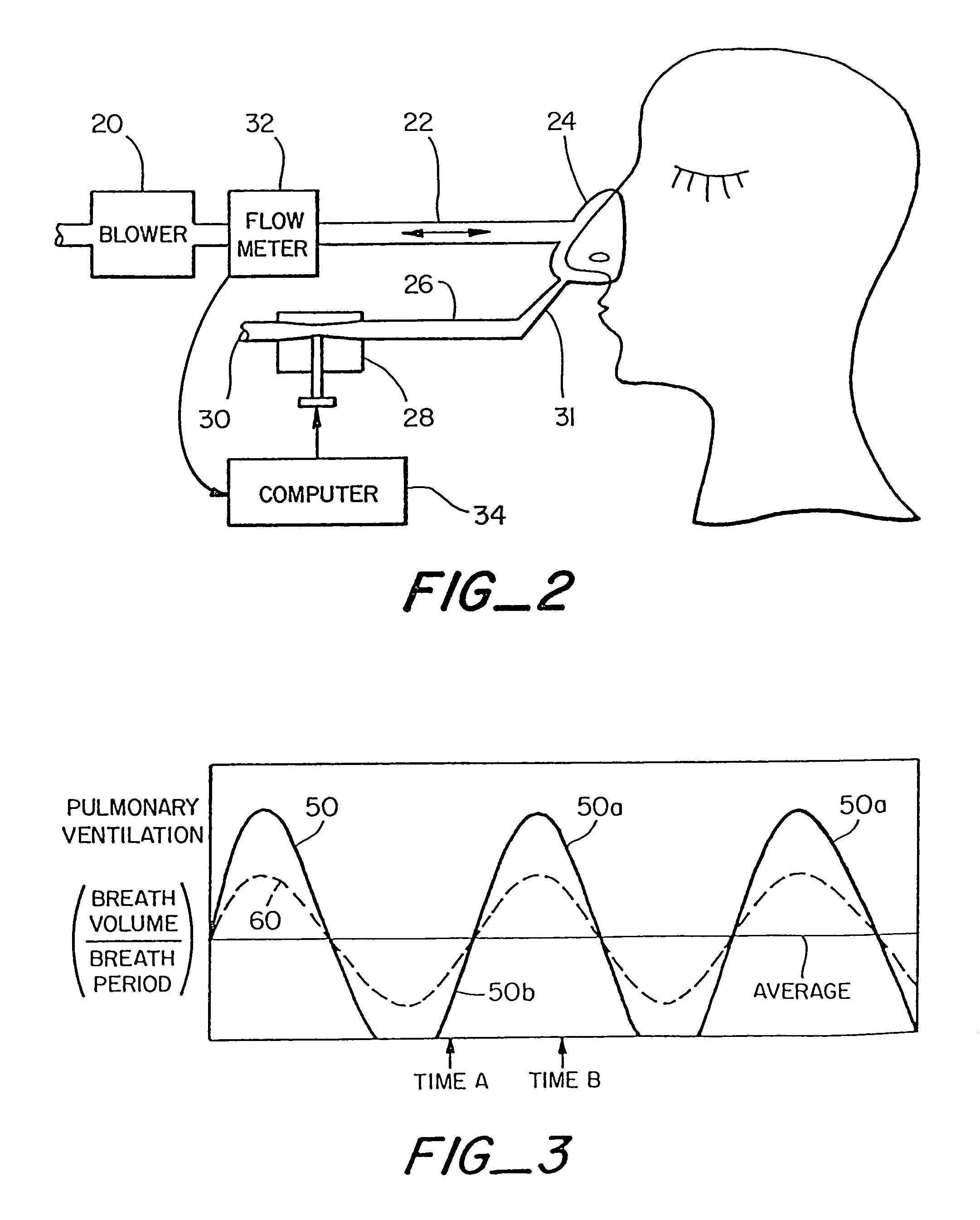
[0040]FIG. 2 is a diagram illustrating the rebreathing apparatus of one active control embodiment of the present invention. In this embodiment, a continuous positive airway pressure apparatus including blower 20, tube 22 and patient interface 24 is used. Patient interface 24, for example a mask or oral interface, preferably produces an airtight tight seal to the face for use in the continuous positive airway pressure treatment. A discussion of continuous positive airway pressure and a preferred continuous positive airway pressure apparatus is described in Remmers, et al. U.S. Pat. No. 5,645,053, “Auto-CPAP Systems and Method for Preventing Patient Disturbance Using Airflow Profile Information.” In conventional CPAP, a blower is used to maintain a relatively high constant pressure in a mask and to provide a bias flow of fresh air from the blower out the mask.

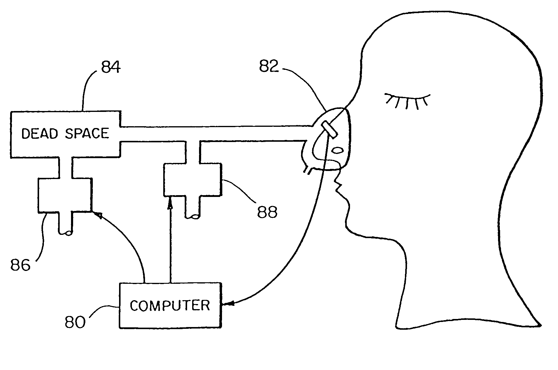
[0041]In one embodiment of the present invention, tube 26 is connected to the exhaust port 31 of the patient interface and cond...


PUM


Abstract

A system for reducing central sleep apnea (CSA) is described in which certain methods of increasing a patient's rebreathing during periods of the sleep cycle are used. By increasing rebreathing during periods of overbreathing, the over-oxygenation which typically results from the overbreathing period can be reduced, thus reducing the compensating underbreathing period and effectively reducing the loop gain associated with the central sleep apnea. Nasal occlusion and a leak resistant oral interface provide control for gas leaks from a patent interface.

Description

CROSS-REFERENCE TO RELATED APPLICATIONS[0001]This application is a continuation-in-part of application Ser. No. 09 / 498,504 filed Feb. 3, 2000, now U.S. Pat. No. 6,752,150.BACKGROUND OF THE INVENTION[0002]Central sleep apnea is a type of sleep-disordered breathing that is characterized by a failure of the sleeping brain to generate regular, rhythmic bursts of neural activity. The resulting cessation of rhythmic breathing, referred to as apnea, represents a disorder of the respiratory control system responsible for regulating the rate and depth of breathing, i.e. overall pulmonary ventilation. Central sleep apnea should be contrasted with obstructive sleep apnea, where the proximate cause of apnea is obstruction of the pharyngeal airway despite ongoing rhythmic neural outflow to the respiratory muscles. The difference between central sleep apnea and obstructive sleep apnea is clearly established, and the two can co-exist. While central sleep apnea can occur in a number of clinical set...

Claims


Application Information

Patent Timeline
IPC IPC(8): A61M16/00A61M16/08A61M16/10
CPCA61M16/00A61M16/0045A61M16/085A61M16/0069A61M2016/0036A61M2016/0042A61M2016/103A61M2210/0625A61M2230/432A62B18/006A61M2210/0618A61M16/026
Inventor REMMERS, JOHN E.HAJDUK, ERIC A.PLATT, RONALD S.
Owner UTI LLP
Why Eureka
Try Eureka