Water pump and thermostatically controlled bypass valve

a technology of thermostatic control and bypass valve, which is applied in the direction of process and machine control, lighting and heating apparatus, instruments, etc., can solve the problems of no method of “draining”, no hot water readily available at the hot water side of the fixture, and no way of bypassing the cold or tepid water. achieve the effect of convenient bypassing of cold or tepid water

Inactive Publication Date: 2006-07-11
GRUNDFOS PUMPS MFG
View PDF21 Cites 42 Cited by
  • Summary
  • Abstract
  • Description
  • Claims
  • Application Information

AI Technical Summary

Benefits of technology

[0015]The water control valve adapted for use with a bypass valve, particularly a thermostatically controlled bypass valve, of the present invention solves the problems and provides the benefits identified above. That is to say, the present invention provides a water control valve adapted for use with bypass valves, including thermostatically controlled bypass valves, to automatically bypass cold or tepid water away from the hot water side of the fixture while the temperature of the water is below the desired level so as to maintain hot water for use at the fixture. The water co...

Problems solved by technology

A well known problem with most home and industrial water distribution systems is that hot water is not always readily available at the hot water side of the fixture when it is desired.
This problem is particularly acute in water use fixtures that are located a distance from the hot water heater or in systems with poorly insulated pipes.
As a result, the temperature of the water between the hot water heater and the fixture lowers until it becomes cold or at least tepid.
For certain fixtures, such as virtually all dishwashers and washing machines (which are not usually provided with a bypass valve), there typically is no method of “draining” away the cold or tepid water in the hot water pipes prior to utilizing the water in the fixture.
The inability to have hot water at the hot water side of the fixture when it is desired creates a number of problems.
One problem is having to utilize cold or tepid water when hot water is desired.
This is a particular problem for the dishwasher and washing machine fixtures in that hot water is often desired for improved operation of those appliances.
Even in those fixtures where the person can let the cold or tepid water flow out of the fixture until it reaches the desired warm or hot temperature, there are certain problems associated with such a solution.
One such problem is the waste of water that flows out of the fixture through the drain and, typically, to the sewage system.
This good and clean water is wasted (resulting in unnecessary water treatment after flowing through the sewage system).
This waste of water is compounded when the person is inattentive and hot water begins flowing down the drain an...

Method used


Image

  • Water pump and thermostatically controlled bypass valve
  • Water pump and thermostatically controlled bypass valve
  • Water pump and thermostatically controlled bypass valve

Examples


example 1

[0073]Shower / Tub Control Valve with Attached Bypass Valve

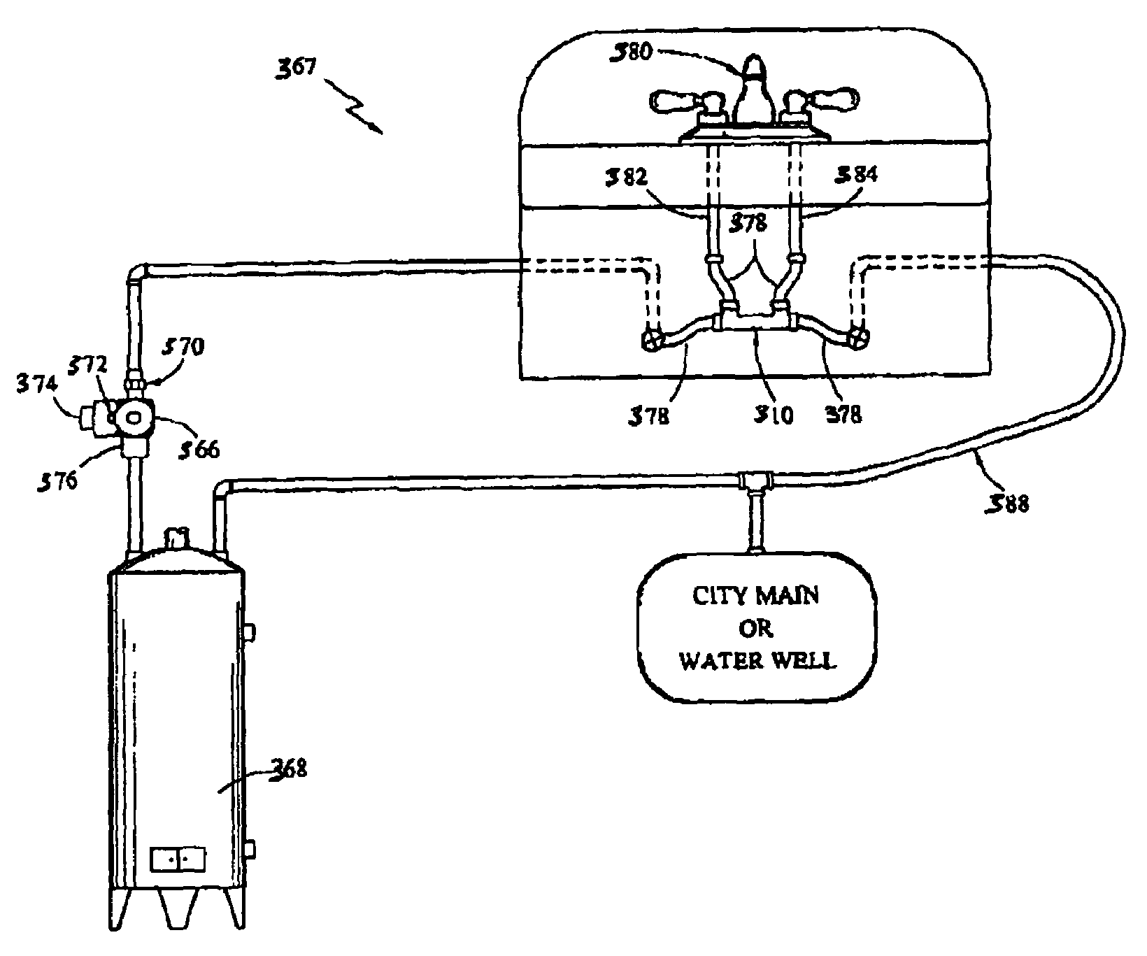
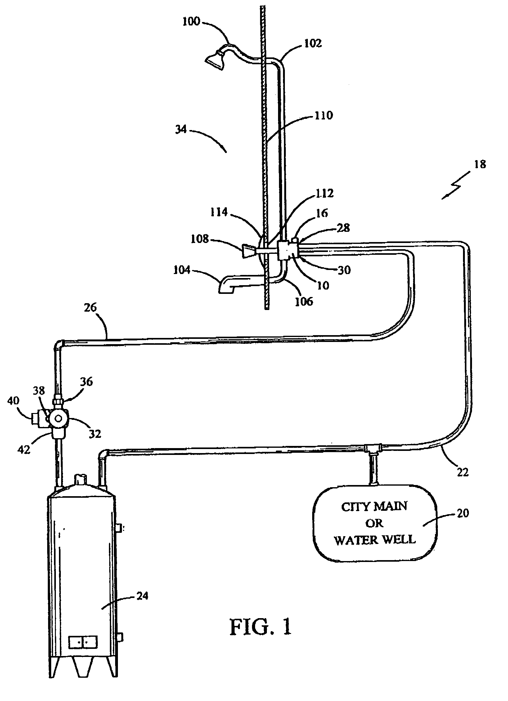
[0074]As is well known, many homes have a combination shower and tub assembly whereby the same water control valve 10 is used to control the flow and temperature to the shower and the tub. A selector valve (not shown) is used to select the flow between the shower and the tub. An example shower / tub system is shown as 34 in FIG. 1. A similar water control valve to that shown as 10, is used for systems comprising only a shower or a tub, with the exception that such valve only has one discharge port (connected to either the shower or the tub). In the shower / tub system 34, water distribution valve 10 with associated bypass valve assembly 98, having bypass valve 16 as described below, distributes water to the shower head assembly 100 through shower line 102 and to tub faucet 104 through tub line 106, as shown in FIG. 1. A flow control valve 108 is used to control the flow and temperature of water to the shower head assembly 100 or t...

example 2

[0087]Shower / Tub Control Valve with Adjacent Bypass Valve

[0088]In the embodiment of the present invention where bypass valve 16 is adjacent to (i.e., but not physically attached to or supported by) water control valve 10, shown in FIGS. 12 and 13, bypass valve 16 is directly supported by first tubular line 156 and second tubular line 158. FIG. 12 illustrates a configuration similar to that shown in FIG. 10 and discussed above except for there is no connecting element 160 or attachment mechanism 162 to affix bypass valve 16 to valve manifold 118. Likewise, FIG. 13 illustrates a configuration similar to that shown in FIG. 11 and discussed above except there is no connecting element 160 or attachment mechanism 162 for affixing bypass valve 16 to valve manifold 118. Depending on the flexibility of first tubular line 156 and second tubular line 158, bypass valve 16 hangs freely from their connection to ports 138 and 140 on water control valve 10 or from first 164 and second 166 bypass co...

example 3

[0090]Service Control Valve

[0091]In the embodiment wherein bypass valve 16 is included with the water control valve, shown as water control valves 12 and 14 in FIGS. 14 through 17, bypass valve 16 is integrated with or appended to a pair of individual water control valves 12, also known as angle stops, or incorporated with a combination water control valve 14. These types of valves are commonly referred to as service valves or non-working valves because they are not operated so as to be frequently moved from the opened to closed positions. Service valves are primarily utilized to connect to washing machines, sinks or faucets on sinks, dishwashing machines and the like apparatuses. Normally, service valves are left in the open position, only being closed to repair or replace the apparatus. In the open position, water is allowed to flow freely to the apparatus, with the apparatus itself having a control valve such as an electrically controlled solenoid valve incorporated therein to co...


PUM


Abstract

A water control valve configured for use with a bypass valve to automatically bypass cold or tepid water in a hot water supply line so as to maintain hot water at the fixture. The water control valve is useful for shower/tub facilities and for appliances such as washing machines and dishwashing machines. The water control valve for use with shower/tub facilities is adapted for the bypass valve to attach to or be adjacent to the water control valve by utilizing bypass ports, passageways and/or connectors. The water control valve for use with appliances is adapted to have a second outlet for connecting to a second water control valve or, for combination service valves, to have the bypass valve disposed in the tubular section between the hot and cold water components. The preferred bypass valve is a thermostatically controlled bypass valve of the type having a thermal actuating element.

Description

CROSS REFERENCE TO RELATED APPLICATIONS[0001]This application is a continuation-in-part of U.S. patent application Ser. No. 10 / 006,970 filed Dec. 4, 2001, (now U.S. Pat. No. 6,929,187) which is a continuation-in-part of U.S. patent application Ser. No. 09 / 697,520 filed Oct. 25, 2000 (now U.S. Pat. No. 6,536,464).BACKGROUND OF THE INVENTION[0002]1. Field of the Invention[0003]The present invention relates generally to water control valves for use in home or industrial water distribution systems that supply water to various fixtures at different temperatures through different pipe systems. More specifically, the present invention relates to such water control valves that are adaptable for use with a bypass valve so as to bypass cold or tepid water away from the associated fixture until it reaches the desired temperature. The present invention is particularly useful for providing a water control valve having a bypass valve which is accessible through the support wall associated with th...

Claims


Application Information

Patent Timeline
IPC IPC(8): F16K49/00E03B7/07E03C1/00F16K31/64
CPCE03B7/09E03B7/045Y10T137/6497Y10T137/7737Y10T137/86815
Inventor KEMPF, DALELUM, KEN
Owner GRUNDFOS PUMPS MFG
Why Eureka
Try Eureka