Ventilation system

a ventilation system and air technology, applied in ventilation systems, lighting and heating apparatus, heating types, etc., can solve the problems of forming ice (crystals), uncomfortable dry air in the building, and affecting the comfort of use,

Inactive Publication Date: 2006-07-11
VENMAR VENTILATION
View PDF11 Cites 57 Cited by
  • Summary
  • Abstract
  • Description
  • Claims
  • Application Information

AI Technical Summary

Benefits of technology

[0050]Advantageously, in terms of relatively lower cost and simplicity, the ventilation apparatus may be configured such that during the defrost cycle the exchanger wheel is stopped, i.e. the exchanger wheel has a rotational speed of 0 rpm. Thus a ventilation apparatus of the present invention may comprise a component for stopping, during a defrost cycle, a rotary exchanger wheel from rotating.
[0061]The above method is advantageous for use in cool weather, such as for example when ambient air temperature is −15° C. or lower (e.g. −15° C. to −25° C.). For this method the exhaust air may be dried using a first desiccant exchanger before it is passed through a subsequent sensible heat exchanger for additional cooling due to the transfer of sensible heat to incoming cool fresh air. Since the air initially heating the incoming air is relatively dry the possibility of the subsequent exchanger icing up may be reduced; on the other hand since the warmed incoming air to which the moisture is being transferred by the first rotary exchanger has been pre-heated the possibility of the desiccant exchanger icing up may also be reduced. This type of method may therefore be used for relatively longer periods of time at very cool ambient air temperatures before having to revert to a defrost cycle. Advantageously, the desiccant exchanger may be configured as a rotary exchanger wheel; any other suitable or known desiccant configuration may however of course be used.
[0077]Preferably, a desiccant wheel will have a high as possible rate of efficiency with respect to the transfer of water to the incoming cool air, e.g. 80%; lower efficiency wheels may of course be used if so desired, keeping in mind, however, that the drier the air is, which is sent to the sensible exchanger, the longer the time interval is between defrostings.
[0113]As may be appreciated from the above, this other aspect of the present invention provides for the possibility of not having to adjust the speed of the rotating wheel for the purposes of a defrost cycle; speed adjustment could of course still be done if desired. For simplicity, however, the wheel may be allowed to continue to rotate at a speed which is normal for a ventilation cycle. In this case, since the defrost air is made to by-pass the fresh path defined by the rotating exchanger wheel the defrost air does not take heat back from the wheel prior to being returned to the building; in this way the possibility that the wheel may lose heat back to the defrost air sent back to the building is avoided.
[0140]second adjustable damper component for adjusting air flow through the exhaust air path means; the presence of such dampers in the ventilator itself will eliminate the necessity of the balancing technician from having to install dampers and remove them as necessary.

Problems solved by technology

Accordingly, if cool dry outside air is brought into a building and the warm moist interior air of the building is merely exhausted to the outside, the air in the building may as a consequence become uncomfortably dry.
However, a problem with such heat recovery ventilation equipment having a desiccant type heat exchanger wheel, is the production of frost or ice in the air permeable heat exchange matrix of the thermal wheel.
However, the cooling of the relatively moist interior air by the cold exterior air can result in the formation of ice (crystals).
An uncontrolled buildup of ice within the matrix of a rotary exchanger wheel can result in decreased heat transfer, and even outright blockage not only of the exhaust air path but the (cold) fresh air path as well.
However, during the defrost cycle, the stale inside air is still exhausted to the outside via the exhaust air path; this is disadvantageous since by blocking only the fresh air inlet and continuing to exhaust interior air to the outside, a negative air pressure can be built up in the interior of a building relative to the exterior atmosphere.
Such a negative pressure may induce uncontrolled entry of air through any cracks and cranies in the structure of the building; the negative pressure may, in particular, produce a backdraft effect, for oil and gas type heating systems, whereby exterior air may be pulled into the chimney leading to the accumulation of gaseous combustion products in the building.
However, it has been found that adapting the technique shown in U.S. Pat. No. 5,193,610 to a rotating heat exchanger wheel by directing interior defrost air through the defrost side of the wheel and then returning the air to the building by passed it through the fresh air side of the wheel while the wheel is rotating at its usual operational or ventilation cycle rotational speed (e.g. a usual ventilation speed of 15 rpm) does not produce the desired degree or efficiency of defrosting; in this case, heat which is initially taken up by the wheel from the warm interior building air is transferred back to the interior air prior to the air being recycled to the interior of the building such that the full heat of the interior air is not utilised for defrosting.
If the usual rotational speed mentioned above is maintained, defrosting occurs over a relatively significant time period (e.g. a defrost time of 18 minutes or more) relative to the ventilation time period (e.g. a ventilation time of 32 minutes) during which the apparatus is operating; i.e. the defrosting period may represent more than 25% of the ventilation operating time which means that this defrosting technique is relatively inefficient keeping in mind that during such defrosting, the system is not carrying out its primary function, namely the ventilation of a room or building.
Another problem with respect to ventilation systems comprising a heat exchanger element or core relates to the installation of an exchanger device in a building such as for example a house or other type of building.
This procedure as may be appreciated is time consuming and may take up to an hour or more of a technician's time.

Method used


Image

  • Ventilation system
  • Ventilation system
  • Ventilation system

Examples


Embodiment Construction

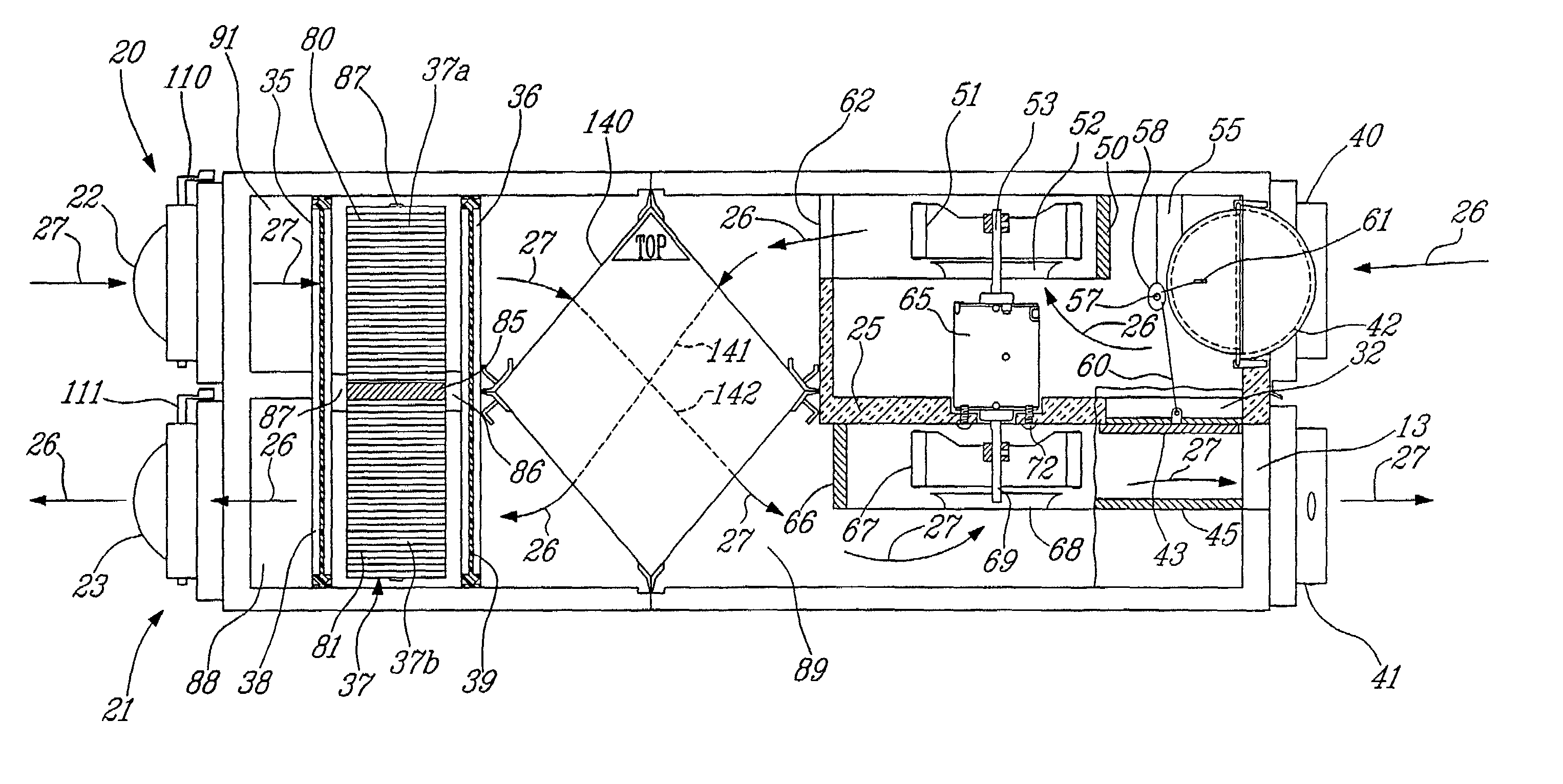
[0182]FIG. 1 shows a ventilation apparatus of the present invention which includes both a defrost means and air flow balancing means.

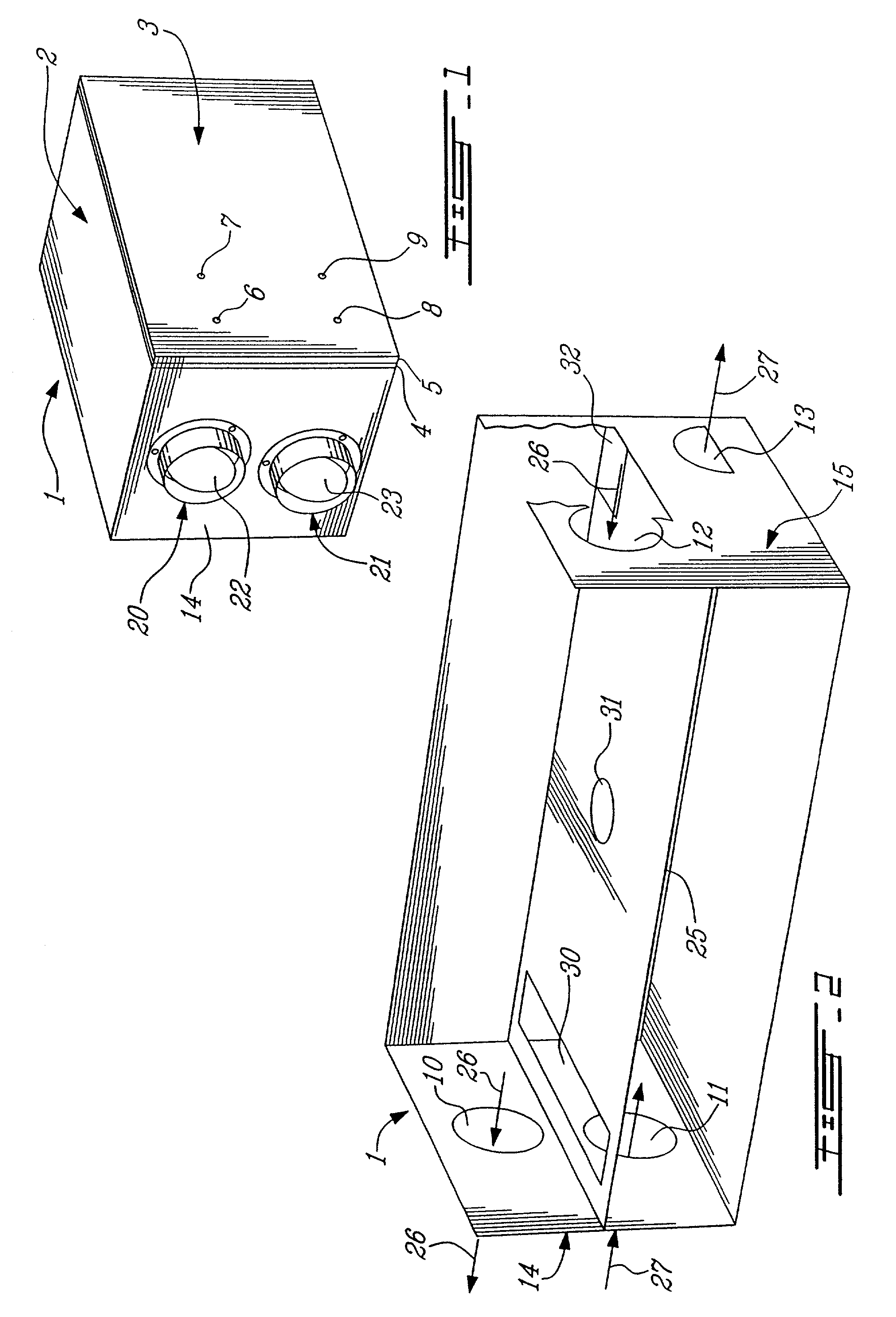
[0183]The apparatus shown in FIG. 1 includes a cabinet indicated generally by the reference number 1. The cabinet 1 is preferably provided with insulated walls and partition wall members.

[0184]The cabinet 1 has a top outer wall 2 and a front door 3. The door 3 is of composite construct comprising a sheet metal outer element 4 and an inner element 5. The inner element 5 is of sheet foam material and is sized to cover the entire inner surface of the element 4. The foam element 5 acts to provide an airtight seal for the door along its periphery adjacent the other walls of the cabinet; element 5 also acts as a heat insolation member. Although not shown, the door may be hingedly attached to hinge members and may be kept shut for example by snap locking members which cooperate with members on the door; see for example U.S. Pat. No. 5,193,610.

[0185]The cabine...


PUM


Abstract

An apparatus for ventilation systems includes an element for the transfer of heat from warm exhaust air (taken from inside a building) to cooler exterior fresh air which is drawn into the building. The present invention in particular provides an apparatus whereby, during a defrost cycle, interior air may circulate through both of the fresh air and exhaust air paths for delivery back into the building, i.e. the warm interior air, used as defrost air, may be able to circulate from the interior of the building into the ventilation apparatus and back to the interior of the building. The apparatus can thus use interior air as defrost air while diminishing or avoiding the creation of a negative air pressure in the building.

Description

[0001]This application is a division of pending prior application U.S. Ser. No. 09 / 770,021, filed on Jan. 25, 2001, which is a continuation of U.S. Ser. No. 08 / 329,124, filed on Oct. 25, 1994, now U.S. Pat. No. 6,209,622, which claims priority fmm Canadian Application Ser. No. 2,134,168, filed Oct. 24, 1994 of Frederic Lagace, et al.BACKGROUND OF THE INVENTION[0002]The present invention generally relates to an apparatus for ventilation systems which have means for the transfer of sensible heat and / or water moisture between exhaust air (taken from inside a building) and exterior fresh air (drawn into the building). Such an apparatus may, for example, have means for the transfer of sensible heat and / or water moisture from warm exhaust air to cooler exterior fresh air, the systems using warm interior air as defrost air for defrosting the systems during cool weather.[0003]The present invention, in one particular aspect, relates to an apparatus for ventilation systems which have at least...

Claims


Application Information

Patent Timeline
Patent Type & Authority Patents(United States)
IPC IPC(8): F23L15/02F24H3/02F24F3/14F24F11/00F24F12/00
CPCF24F3/1423F24F11/0086F24F12/006F24F2011/0002F24F2011/0087F24F2203/1004Y02B30/563F24F2203/1032F24F2203/104F24F2203/1068F24F2203/1084Y10S165/909F24F2203/1012F24F11/30F24F11/41Y02B30/56
Inventor LAGACE, FREDERICGRONDIN, JEAN-FRANCOISCUSSON, PIERREJULIEN, MICHELMARCOUX, DANIEL
Owner VENMAR VENTILATION
Why Eureka
Try Eureka