Automotive heat exchanger

a heat exchanger and auto-type technology, applied in indirect heat exchangers, lighting and heating apparatuses, laminated elements, etc., can solve the problems of reducing the cooling efficiency, reducing and reducing the relative high pressure drop of oil, so as to improve the cooling efficiency of oil and reduce the length or number of tubes. required

Active Publication Date: 2006-07-11
HANON SYST
View PDF22 Cites 22 Cited by
  • Summary
  • Abstract
  • Description
  • Claims
  • Application Information

AI Technical Summary

Benefits of technology

[0005]This invention provides a heat exchanger for an automotive vehicle that includes an oil cooler section, preferably in combination with a separate section for cooling a different fluid, such as a condenser section for an air conditioning system. The heat exchanger includes a first manifold and a second manifold that are spaced apart, and a plurality of tubes that extend between the manifolds and define fluid passages in fluid communication with chambers within the manifolds. At least a portion of the tubes define oil flow passages for the oil cooler section and are adapted for conveying oil. In accordance with this invention, the oil cooling tubes have a cross section characterized by a performance ratio between about 3.9 and 8.5. As used herein, the performance ratio is based upon a cross-section of the tube and refers to the ratio of the wetted perimeter of the oil flow passage in millimeters divided by the cross sectional area of the metal of the tube, that is, excluding the area of the oil flow passage. By utilizing tubes having a performance ratio within the recited range, the heat exchanger improves the cooling efficiency for oil and thereby reduces the length or number of tubes required to achieve a desired cooling effect.

Problems solved by technology

Small cross sectional paths, such as found in condenser tubes, result in a relatively high pressure drop for the oil.
This reduces cooling efficiency and necessitates an increase in either the length or number of tubes to achieve the desired temperature drop.

Method used


Image

  • Automotive heat exchanger
  • Automotive heat exchanger
  • Automotive heat exchanger

Examples


Embodiment Construction

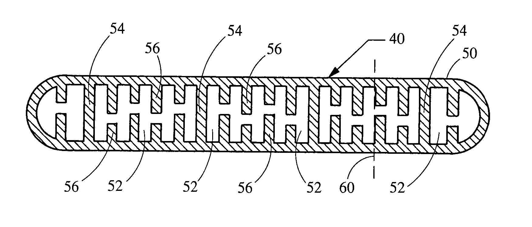
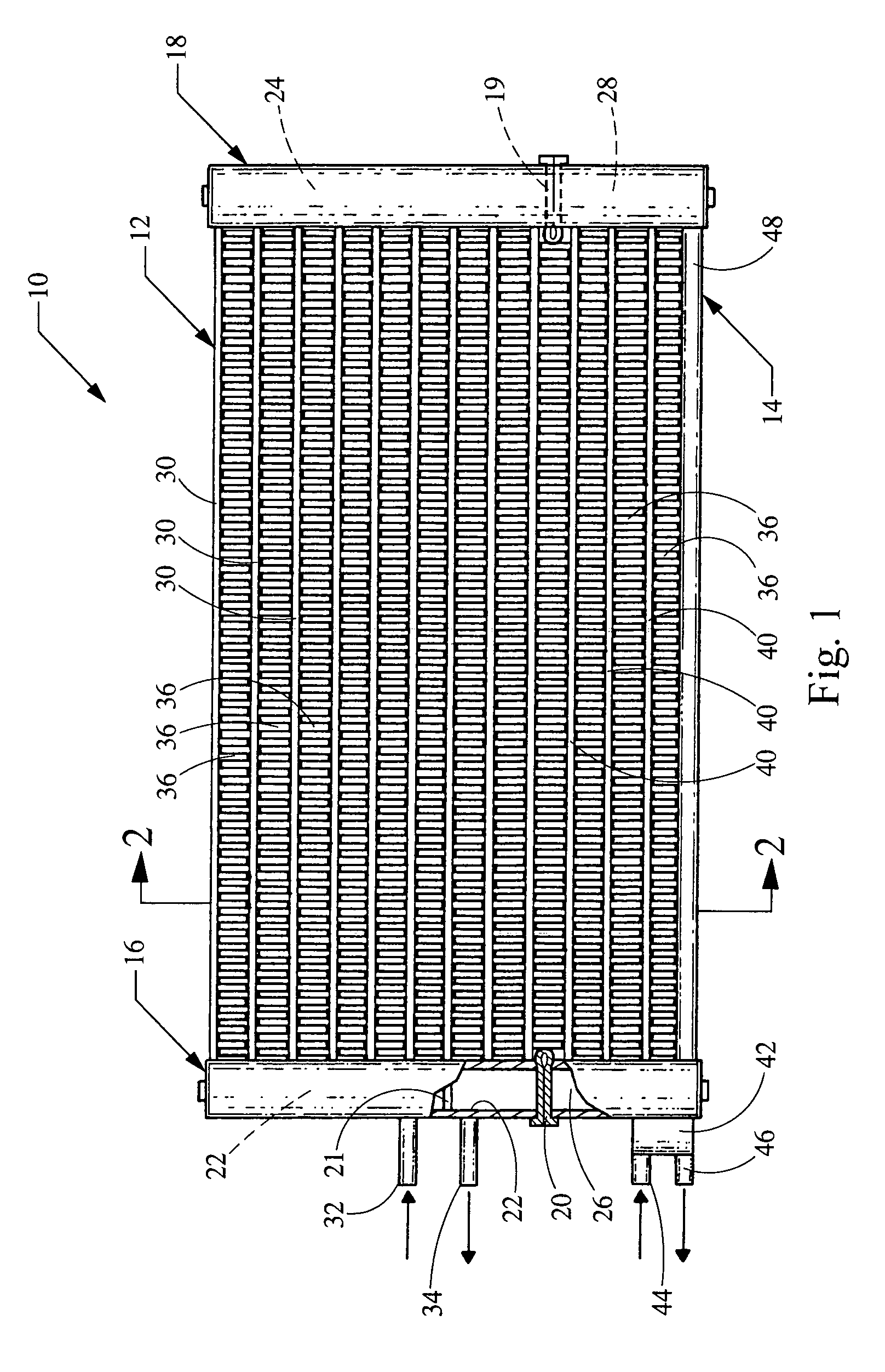
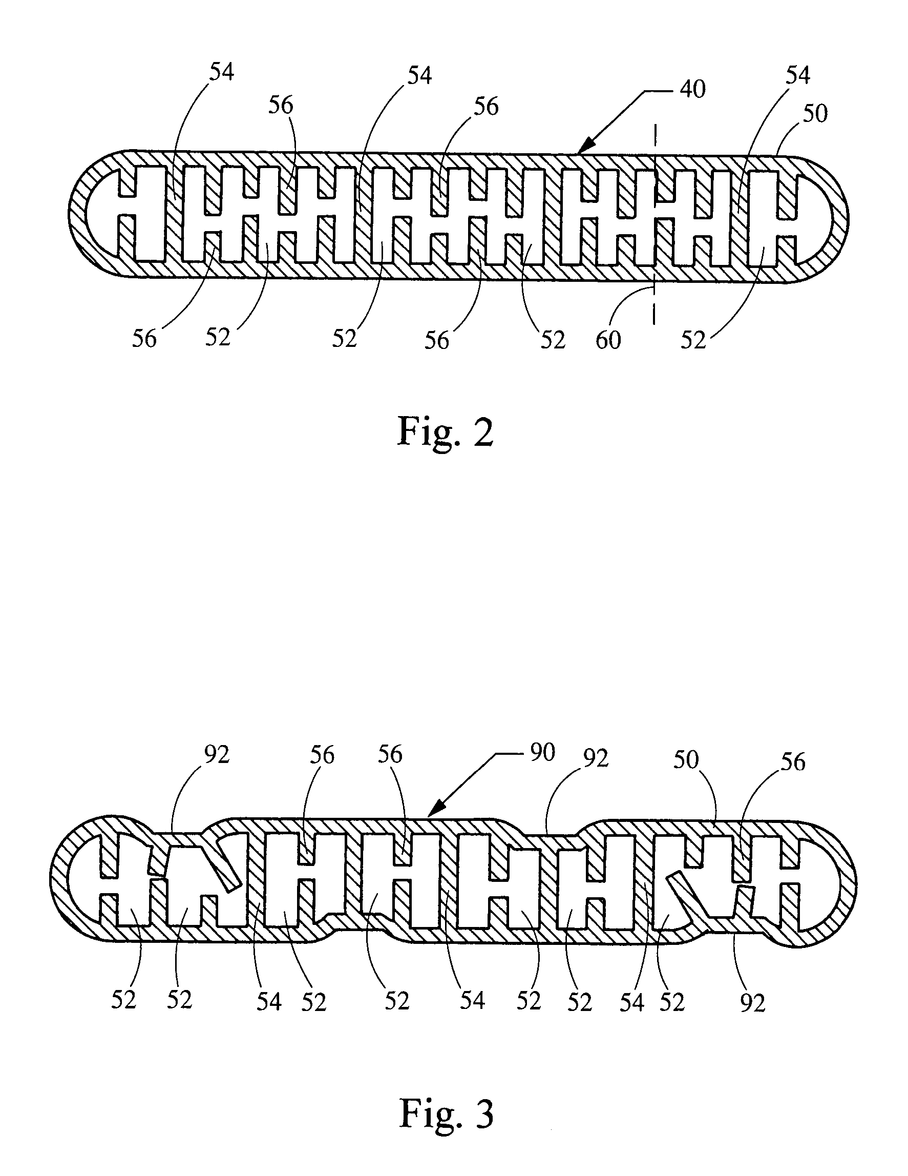
[0012]In accordance with a first preferred embodiment of this invention, referring to FIGS. 1 and 2, a combination heat exchanger 10 is adapted for use in an automotive vehicle and includes a first section 12 and a second section 14 for cooling different fluids. In a preferred embodiment, section 12 is a condenser for cooling refrigerant for an air conditioning system. Also in a preferred embodiment, section 14 is adapted for cooling transmission oil, and is referred to herein as a transmission oil cooler section. Alternately, heat exchanger 10 may be adapted for cooling other fluids.

[0013]Heat exchanger 10 comprises a first manifold 16 and a second manifold 18 in spaced, parallel relationship. Baffles 19 and 20 divide each manifold 16 and 18 into first chambers 22 and 24 for condenser section 12 and second chambers 26 and 28 for oil cooling section 14. In addition, the manifolds may include baffles, for example, baffle 21 that further divide the chambers into portions for routing t...


PUM


Abstract

A heat exchanger includes a first section and a second section for cooling distinct fluids, wherein the second section is adapted for cooling oil. The heat exchanger includes first and second manifolds divided by baffles into first and second chambers. A plurality of tubes connect the manifolds in fluid communication with the first chambers to form the first section of the heat exchanger. A plurality of oil cooling tubes connect the manifolds in fluid communication with the second chambers to form the second section. The oil cooling tubes have a cross-section characterized by a performance ratio between about 3.9 and 8.5 wherein the performance ratio is the ratio of the wetted perimeter in millimeters divided by the cross-sectional area of tube metal in square millimeters. The oil cooling tubes may be formed of extruded metal with internal fins or an extruded tube having a stamped metal insert.

Description

TECHNICAL FIELD OF THE INVENTION[0001]This invention relates to a heat exchanger that includes an oil cooler section, and, more particularly, to an oil cooler section that includes tubes having an improved performance ratio.BACKGROUND OF THE INVENTION[0002]An automotive vehicle comprises one or more heat exchangers for cooling fluids used in the vehicle systems, such as refrigerant for an air conditioning system or transmission oil for a transmission device. A common heat exchanger comprises a plurality of parallel tubes connected at each end to a manifold and spaced apart by corrugated fins. Typically the tubes are formed of extruded aluminum. The manifolds include an inlet for receiving the fluid to be cooled and an outlet for supplying cooled fluid to other components in the system. The fluid enters the manifold through the inlet and is distributed to flow through passages within the tubes. Heat is extracted by air that flows through spaces between the corrugated fins between the...

Claims


Application Information

Patent Timeline
Patent Type & Authority Patents(United States)
IPC IPC(8): F28F1/42F28F1/10F28D1/04F28D1/053F28F1/02F28F3/04F28F13/12
CPCF28D1/0443F28F1/022F28F1/42F28F3/044F28F3/048F28F13/12F28F1/422F28D2021/0084F28D2021/0089Y10S165/916F28F2009/0287F28F2215/04
Inventor YU, WEN FEILOHMEYER, III, LORENELIADES, MANOSRIDDLE, II, JACK H.
Owner HANON SYST
Why Eureka
Try Eureka