
Method of aligning inkjet nozzle banks for an inkjet printer

a technology of inkjet printing and nozzle bank, which is applied in the field of methods and inkjet printing, can solve the problems of relatively poor image quality, relatively complex fabrication of pagewidth inkjet printheads, and not gained a large following, and achieve the effect of reducing image artifacts

Inactive Publication Date: 2006-07-11
EASTMAN KODAK CO
View PDF17 Cites 69 Cited by
  • Summary
  • Abstract
  • Description
  • Claims
  • Application Information

AI Technical Summary

Benefits of technology

The invention provides methods for reducing image artifacts in printers that employ multiple nozzle banks. The methods involve printing dots on a receiver medium from different nozzle banks and adjusting the alignment of the nozzle banks accordingly to correct any placement errors. The methods can be applied to inkjet printers that use a single nozzle bank or multiple nozzle banks. Additionally, the invention provides methods for aligning the printing of pixels by different nozzle banks and adjusting the alignment of the nozzle banks accordingly.

Problems solved by technology

Today the fabrication of pagewidth inkjet printheads is relatively complex and they have not gained a broad following.
In addition there are problems associated with high-resolution printing in that simultaneous placement of ink drops adjacent to each other can create coalescence of the drops resulting in an image of relatively poor quality.
If they are not well registered, then the maximum density attainable by the printer will be compromised and banding artifacts will appear.
Even more troublesome is a slight, relative skew between the two nozzle banks as shown in FIG. 5.
At the other end of the swath, however, poor registration is incurred and banding is observed with a period equal to the height of the swath.
Even very slight misalignments can result in objectionable image artifacts.
Large physical separations between two nozzle banks can make proper alignment even more difficult.
Requiring precise alignment of two sets of nozzle banks being separated by such a distance is very challenging using typical techniques.
These are just some of the ways that the image quality produced by an inkjet printer can be compromised by poor registration of the various nozzle banks.
Additionally, poor registration between the color planes can result in blurry or noisy images and overall loss of detail.
These problems make good registration and alignment of all the nozzle banks within an inkjet printer critical to ensure good image quality.
However, this adds to the number of nozzle banks that must be aligned, thereby increasing the possibility for misalignment and the labor required to properly align all the nozzle banks.
This does not increase the count of nozzle banks, but usually results in longer nozzle banks as increasing the nozzle density of a nozzle bank typically requires a completely new print head design and / or a new manufacturing process.
Longer nozzle banks also increase the difficulty of alignment of the nozzle banks as the sensitivity to angular displacements increases proportionately.
These sensitivities further complicate the nozzle bank alignment process.
Yet another complicating factor is the use of multiple drop sizes of which many new print head designs are capable.
Visual techniques are disadvantaged in many ways.
First, for a printer with many nozzle banks (24 separate nozzle banks is not uncommon), multiple print head heights, and multiple carriage velocities, the number of alignments can become overbearing as each variation adds multiplicatively to the rest.
Secondly, only a moderate level of accuracy is attainable with most of these techniques and finely tuned printers require a higher degree of accuracy attainable by most of these techniques.
The level of accuracy is further compromised between all color records by using a single color as the only reference.
Thirdly, interactions can occur between the various alignment parameters, which further degrade the ultimate quality of alignment that can be obtained through these visual techniques, or multiple iterations are required, thereby increasing the labor of the effort.
Firstly, they require additional hardware costs for each printer as a separate optical sensor and accompanying electronics are required.
Secondly, the optical sensors are typically of the LED variety with economical optics and cannot provide the high degree of accuracy required of finely tuned, high-end printers.
Thirdly, these sensors require significant averaging to create a reliable signal, making the amount of receiver required to perform the alignment larger than one would desire.
Furthermore, this high degree averaging necessitates a separate measurement for each nozzle bank, requiring even more ink and receiver as the number of nozzle banks increases.
Some techniques provide means by which slow-scan misalignments may be determined, but these measurements require separate, additional patterns, further consuming additional ink and receiver.
Furthermore, this fast-scan limitation makes determination of nozzle bank skew very difficult or impossible (U.S. Pat. No. 5,250,956, for example, requires 8 separate measurements to ascertain nozzle bank skew and U.S. Pat. No. 6,076,915 makes no provision for measurement of skew) and, as demonstrated in FIG. 5, this is a critical alignment dimension.
Another result of the fast-scan directional limitation is the inability to measure errors in the advance of the receiver, yet another critical alignment variable.
While effective at detecting print head performance problems, it is incapable of detecting minute alignment errors shown to be detrimental in inkjet printing using multiple nozzle banks.
Additionally, the invention disclosed in U.S. Pat. No. 6,347,857B1 requires additional printer hardware and special receiver for the analysis, adding to total printer cost.

Method used


Image

  • Method of aligning inkjet nozzle banks for an inkjet printer
  • Method of aligning inkjet nozzle banks for an inkjet printer
  • Method of aligning inkjet nozzle banks for an inkjet printer

Examples


Embodiment Construction

[0056]The present description will be directed in particular to elements forming part of, or cooperating more directly with, apparatus and methods in accordance with the present invention. It is to be understood that elements not specifically shown or described may take various forms well known to those skilled in the art.

[0057]In the specification, various terms are employed and are defined as follows:

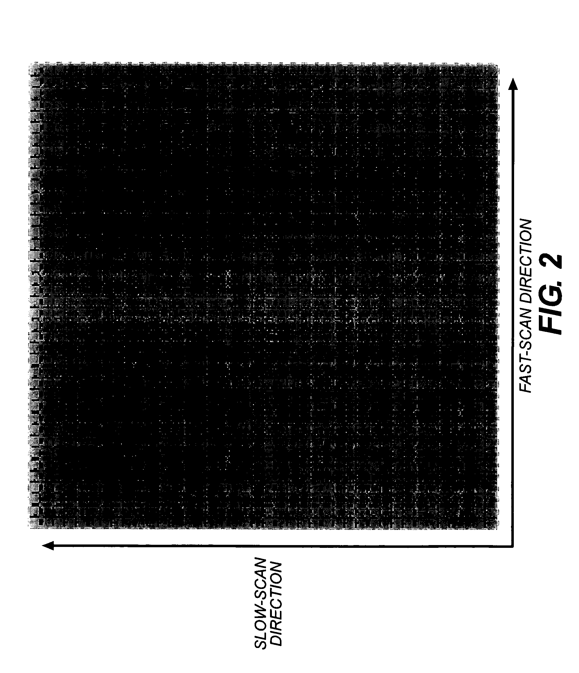
[0058]The term “banding” refers to an imaging artifact in which objectionable lines or density variations are visible up and in the image. Banding may occur as vertical banding or horizontal banding, the horizontal direction coinciding with the fast scan direction and the vertical direction coinciding with the slow scan direction.

[0059]The term “dot size” relates to the size of a printed dot and may be determined by thresholding a digitized target containing the dots, the dot size may be expressed as an area, diameter, or other convenient metric. Dot size may be inferred from optical ...


PUM


Abstract

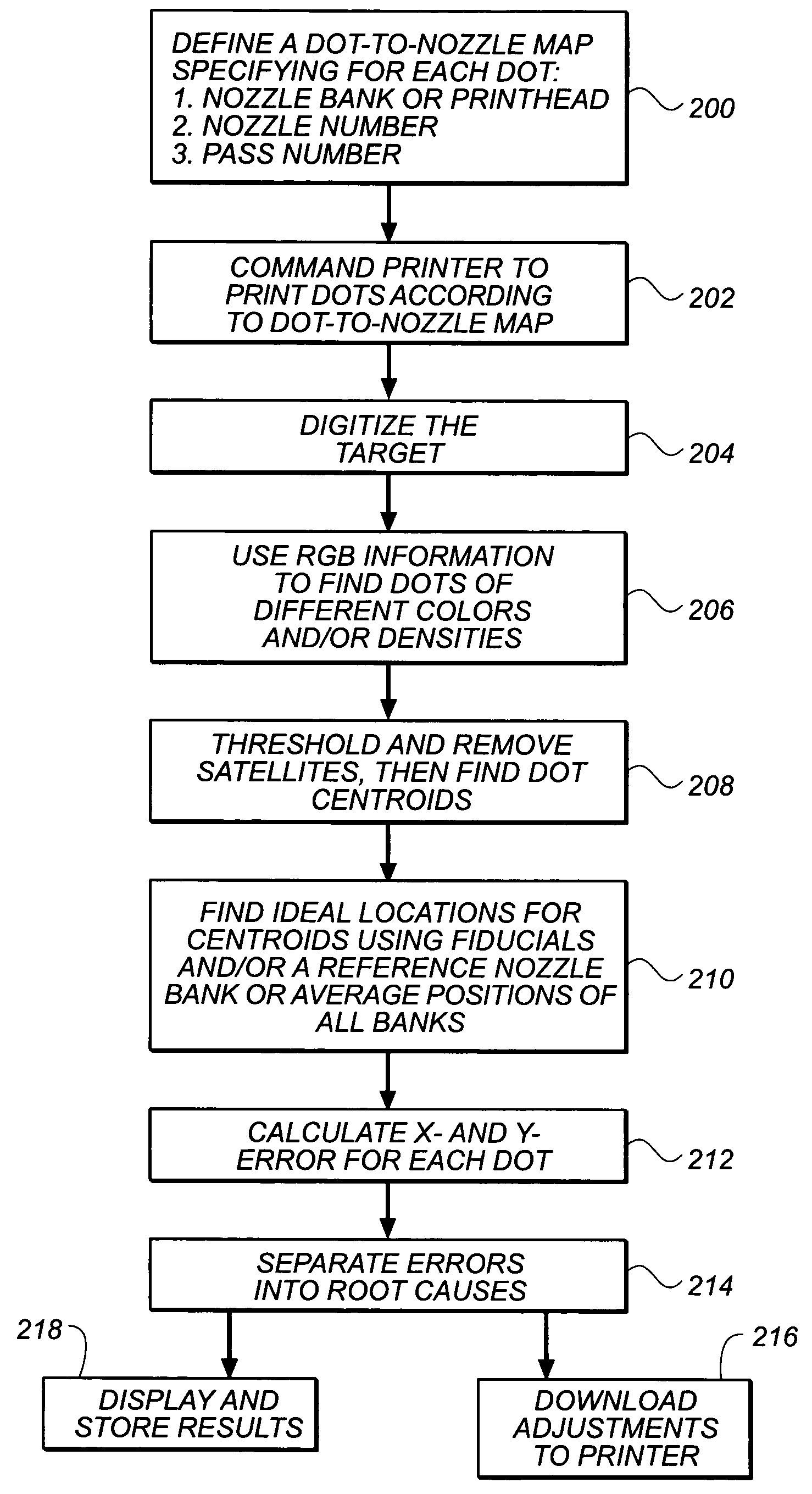
A method is provided for reducing image artifacts in printers that employ two or more printhead nozzle banks that must be aligned and registered with respect to each other either through adjustment of orientation and / or position of one nozzle bank relative to another or through selective control of actuation. In the method, discrete dots are printed by the nozzle banks upon a target receiver medium. Examination of the receiver medium or a reproduction thereof is made by a scanner and information regarding location of the dots is generated. From information regarding location of the dots a determination is made of error placement of the dots from ideal locations. Alignment of the nozzle banks are made in accordance with any errors determined in placement.

Description

FIELD OF THE INVENTION[0001]The invention relates generally to the field of printing such as for example inkjet printing and more particularly, in the field of inkjet printing, to a method of aligning inkjet nozzle banks or modules within an inkjet printer. As broadly used herein alignment of a nozzle bank can be controlled by the adjustment of orientation and / or position of the nozzle bank as well as through selective control of actuation of respective nozzles of the nozzle bank to control proper dot placement.BACKGROUND OF THE INVENTION[0002]Inkjet printing is a non-impact method for producing images by the deposition of ink droplets in a pixel-by-pixel manner into an image-recording element in response to digital signals. There are various methods which may be utilized to control the deposition of ink droplets on the receiver member to yield the desired image. In one process, known as drop-on-demand inkjet printing, individual droplets are ejected as needed on to the recording me...

Claims


Application Information

Patent Timeline
Patent Type & Authority Patents(United States)
IPC IPC(8): B41J29/393B41J2/145B41J2/15B41J2/21B41J19/14
CPCB41J2/2135B41J25/308B41J19/145
Inventor BILLOW, STEVEN A.
Owner EASTMAN KODAK CO
Learn More