Dynamic radial capillary seal

Active Publication Date: 2006-07-11
SEAGATE TECH LLC
View PDF6 Cites 15 Cited by
  • Summary
  • Abstract
  • Description
  • Claims
  • Application Information

AI Technical Summary

Benefits of technology

[0013]In a further advantage, the present invention pro

Problems solved by technology

First is the problem of vibration generated by the balls rolling on the bearing raceways.
This vibration results in misalignment between the data tracks and the read/write transducer.
This source of vibration limits the data track density and the overall performance of the disc drive system.
Further, ball bearings are not always scalable to smaller dimensions.
This is a significant drawback, since the tendency in the disc drive

Method used


Image

  • Dynamic radial capillary seal
  • Dynamic radial capillary seal
  • Dynamic radial capillary seal

Examples


Embodiment Construction

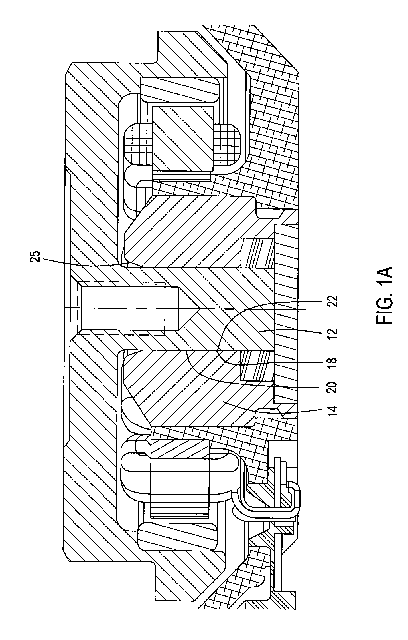
[0026]FIG. 1A illustrates a cross section through a typical motor incorporating a conventional capillary seal at an end of the journal bearing. In this example, the rotating shaft 12 rotates within a sleeve 14. The shaft is supported for rotation by a journal bearing defined in a gap 18 between a surface 20 of sleeve 14 and a facing surface 22 of shaft 12. Fluid in the gap 18 is pressurized by grooves on one of the two surfaces 20, 22 to support the relative rotation of the shaft and sleeve. To retain the fluid in the gap, and to replenish any fluid which may be lost to evaporation, a capillary seal 25 of known design is provided, defined by the diverging walls of 18, 22 of the shaft and sleeve. It is readily apparent that the axial length of the capillary seal noticeably diminishes the axial length available for the journal bearing.

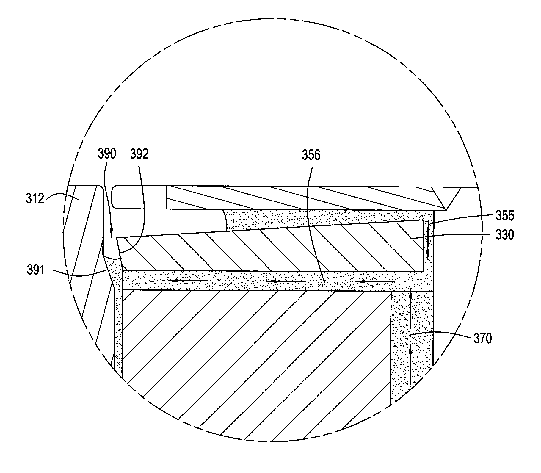
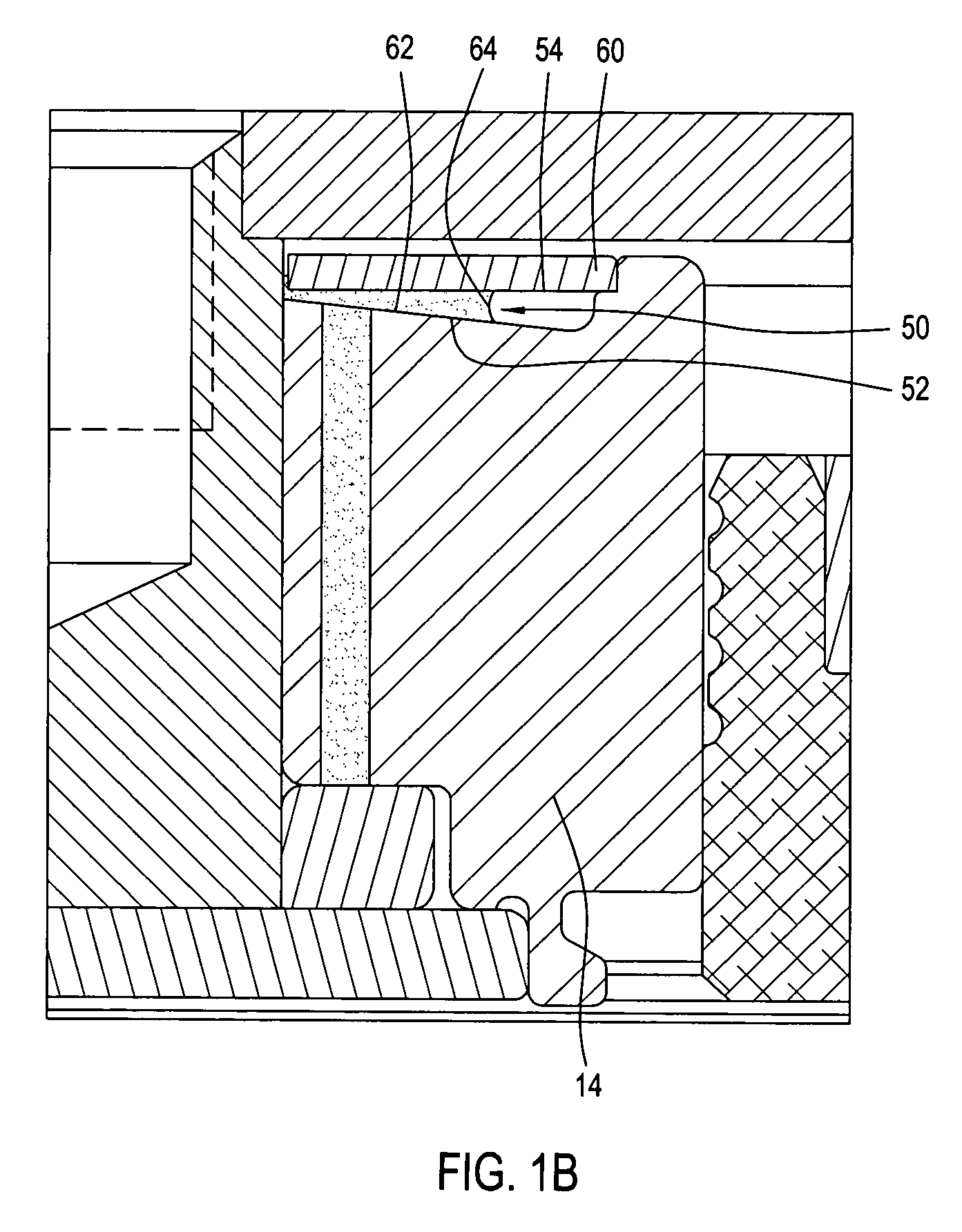
[0027]FIG. 1B is a partial sectional view of a radial capillary seal as it would appear if incorporated in a rotating shaft motor of the design of FIG. ...


PUM


Abstract

A fluid dynamic bearing motor is provided that comprises a stationary member, a rotating member that is configured to rotate about a rotational axis, a fluid dynamic bearing that is configured to support relative rotation between the stationary member and the rotating member, and a dynamic radial capillary seal defined at least in part by the rotating member.

Description

CROSS REFERENCE TO RELATED APPLICATIONS[0001]This application claims the priority of U.S. Provisional Application Ser. No. 60 / 424,214, filed Nov. 5, 2002 by Aiello et al. (entitled “Dynamic Radial Capillary Seal For FDB Motors”), which is herein incorporated by reference.FIELD OF THE INVENTION[0002]The present invention relates generally to fluid dynamic bearing motors, and relates more specifically to small form factor fluid dynamic bearing motors that utilize radial capillary seals.BACKGROUND OF THE INVENTION[0003]Disc drive memory systems have been used in computers for many years for storage of digital information. Information is recorded on concentric tracks of a magnetic disc medium, the actual information being stored in the forward magnetic transitions within the medium. The discs themselves are rotatably mounted on a spindle, while the information is accessed by read / write heads generally located on a pivoting arm which moves radially over the surface of the rotating disc. ...

Claims


Application Information

Patent Timeline
IPC IPC(8): F16C33/74F16C17/02F16C33/10G11B19/20
CPCF16C17/02F16C17/045F16C33/74G11B19/2009F16C33/107F16C2370/12F16C33/745F16C17/107
Inventor AIELLO, ANTHONY JOSEPHFLORES, PACO GREGORKLOEPPEL, KLAUS DIETERKHURRAM, ALI
Owner SEAGATE TECH LLC
Why Eureka
Try Eureka