Probe card having a coil spring interposed between a support member and a contactor unit

a coil spring and contactor unit technology, applied in the field of probe cards, can solve the problems of bringing about a defective continuity to the interposer, a deformation or breakage of the contactor unit 300, and a defect in the continuity of the subject to be tested

Inactive Publication Date: 2006-07-11
NIHON DENSHIZAIRYO
View PDF21 Cites 29 Cited by
  • Summary
  • Abstract
  • Description
  • Claims
  • Application Information

AI Technical Summary

Benefits of technology

[0010]The present invention is designed in view of the above-mentioned background, and aims to provide a probe card that prevents a deformation of a component member such as a contactor unit or the like and capable of performing a test under a satisfactory continuity condition.

Problems solved by technology

However, the contactor unit 300 may be deformed or broken in the conventional probe card, in the case where an adjusting stroke is excessively exerted on the parallelism adjusting screw 520 upon adjusting the degree of parallelism.
The deformation or damage of the contactor unit 300 has a problem of entailing non-uniform height of the contactor to thereby bring about a defective continuity to the subject to be tested.
Similarly, the above-mentioned deformation or damage also has a problem of bringing about a defective continuity to the interposer 200.
This deformation is likely to cause an electrically defective continuity.
Further, a temperature difference of each component member is produced in a test under a high temperature, whereby a warp of the overall substrate body is produced by the difference in a distortion amount of each component member based upon this temperature difference, thereby entailing a problem that electrical defective continuity is brought about as a result of this warp.
This problem is eliminated by using a material having a coefficient of thermal expansion adjusted corresponding to the temperature difference of each component member so as to prevent the occurrence of the warp, but it is practically impossible to completely prevent the occurrence of the warp by finely adjusting the coefficient of thermal expansion of the material.

Method used


Image

  • Probe card having a coil spring interposed between a support member and a contactor unit
  • Probe card having a coil spring interposed between a support member and a contactor unit
  • Probe card having a coil spring interposed between a support member and a contactor unit

Examples


first embodiment

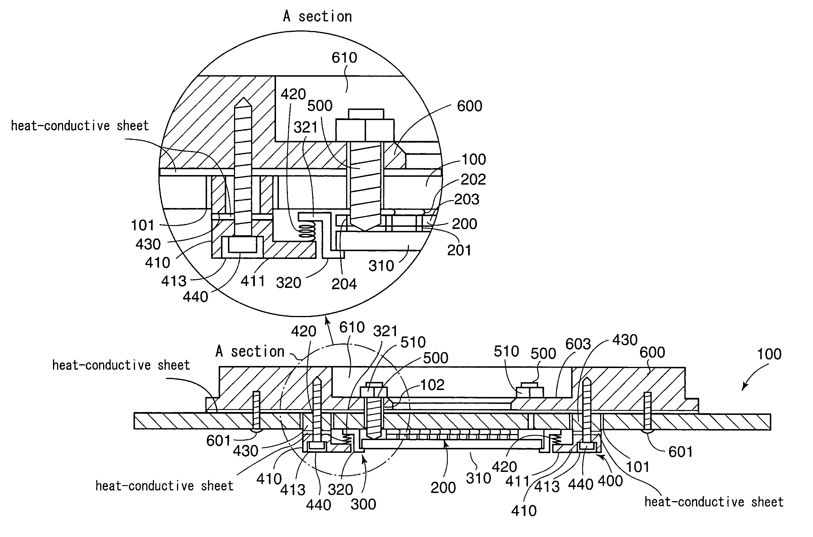
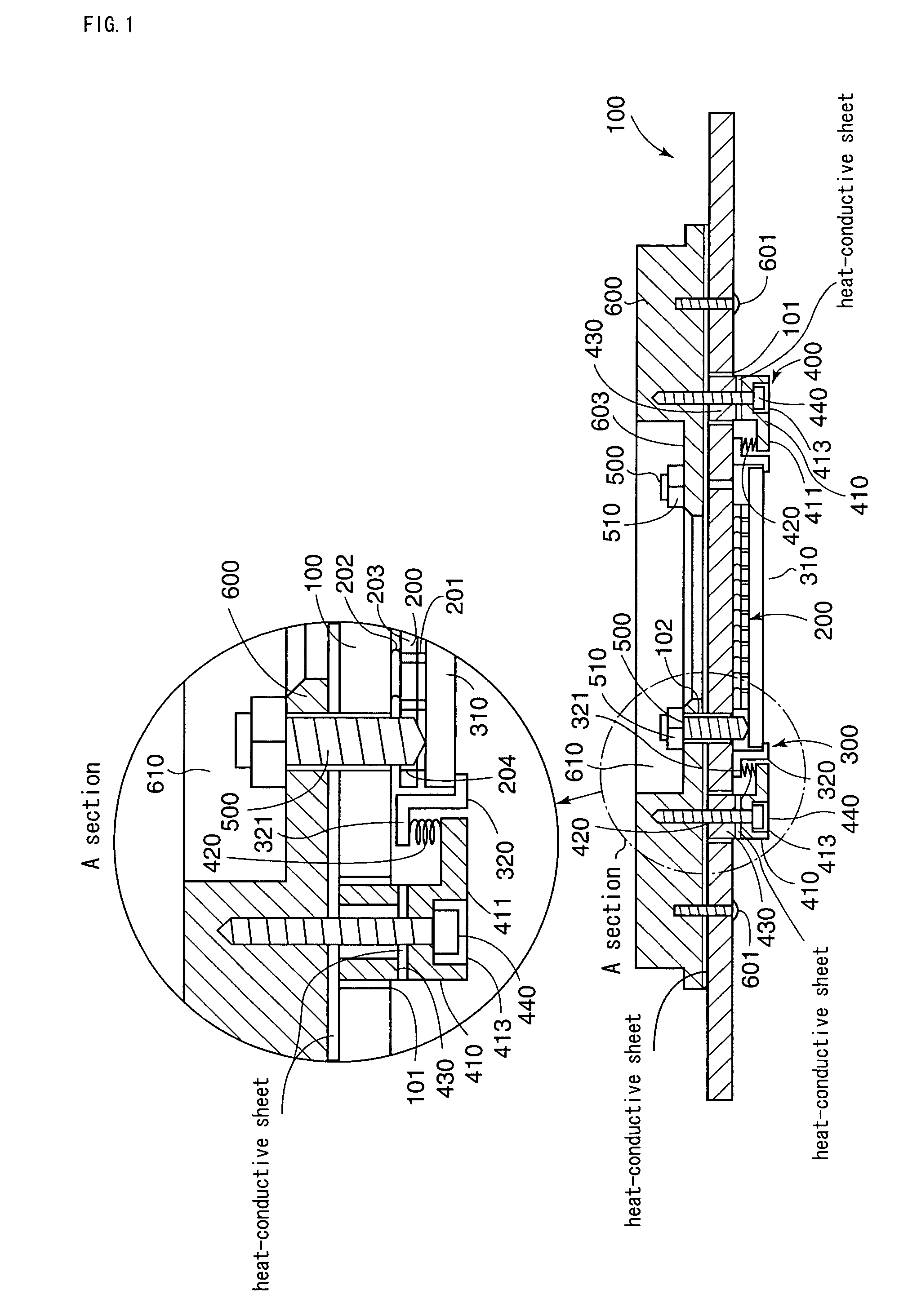
[0021]A probe card according to the first embodiment is used for performing an electrical test of a subject to be tested that is a semiconductor device or the like and comprises a substrate body 100, a contactor unit 300 provided below the substrate body 100 for establishing an electrical contact with the subject to be tested as well as for establishing an electrical contact with the substrate body 100 via an interposer 200, supporting means 400 for supporting the contactor unit 300 from below with elastic force, a parallelism adjusting screw 500 that serves as parallelism adjusting means and comes in contact with the contactor unit 300 from above in a vertical direction for adjusting a degree of parallelism of the contactor unit 300 and a reinforcing plate 600 (corresponding to a first reinforcing plate) that comes in fixed contact with the upper section of the substrate body 100.

[0022]The substrate body 100 has a wiring pattern or the like formed on its surface and electrically co...

second embodiment

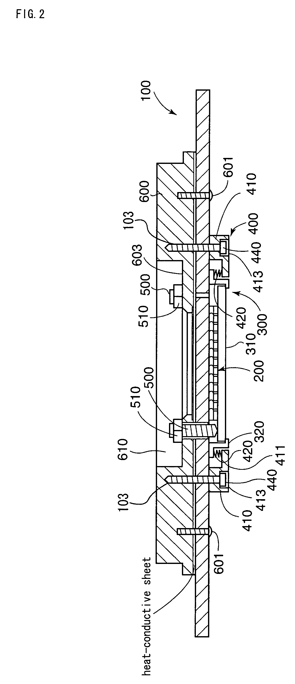
[0034]Subsequently explained is a probe card according to a second embodiment, in which same numerals are given to members having the same configuration and function as those of the first embodiment for omitting their detailed explanations.

[0035]The probe card according to the second embodiment greatly differs from the first embodiment only in that the support member 410 is attached to the reinforcing plate 600 by using the setscrew 440 without using the spacer 430. Because the setscrew 440 is insertedly penetrated into the bore hole 103 formed on the substrate body 100, the elastic force of the coil spring 420 is not directly exerted on the substrate body 100, to thereby be capable of preventing the deformation of the substrate body 100. This is the same as the first embodiment.

[0036]Further, the heat-conductive sheet is interposed between the substrate body 100 and the reinforcing plate 600 and between the substrate body 100 and the support member 410 respectively, thereby being c...

third embodiment

[0037]Subsequently explained is a probe card according to a third embodiment, in which same numerals are given to members having the same configuration and function as those of the first and second embodiments for omitting their detailed explanations.

[0038]The probe card according to the third embodiment greatly differs from the first embodiment only in that a reinforcing plate 630 is attached to the reinforcing plate 600 by set screws 605 for covering the hole 610 and the reinforcing plate 630 has a screw 620 threadedly secured thereto so as to cause its leading edge to be in contact with a section of the substrate body 100 corresponding to a position above the contactor unit 310 via the hole 610. A locking nut 621 is threadedly secured to the screw 620 for preventing a careless rotation. The leading edge of the screw 620 is formed to have a curved surface. Further, a heat-conductive sheet is interposed between the reinforcing plate 600 and the reinforcing plate 630.

[0039]The elast...


PUM


Abstract

A probe card including a substrate body, a contactor unit provided below the substrate body for establishing an electrical contact with the subject to be tested as well as for establishing an electrical contact with the substrate body, a supporting device for supporting the contactor unit from below with elastic force and parallelism adjusting screws that come in contact with the contactor unit from above in a vertical direction for adjusting a degree of parallelism of the contactor unit. In particular, the supporting device is configured to include a coil spring interposed toward a vertical direction between a flange section provided at the inside section of the support member arranged below the substrate body and a flange section provided at the outside section of the contactor unit.

Description

BACKGROUND OF THE INVENTION[0001]1. Field of the Invention[0002]The present invention relates to a probe card for evaluating electrical characteristics of a semiconductor device or the like.[0003]2. Description of the Related Art[0004]In recent years, a plurality of chips are simultaneously tested in a wafer test with a probe card. There has conventionally been well-known a probe card shown in FIG. 4 having a contactor unit 300 including a contactor that establishes an electrical contact with a semiconductor device that is a subject to be tested and a substrate body 100, those of which are discretely fabricated. In this type of probe card, the substrate body 100 and the contactor unit 300 are electrically connected via an interposer 200.[0005]A leaf spring 450 is fixed below the substrate body 100 so that its free end projects inwardly. The contactor unit 300 is supported by the leaf spring 450 from below and has parallelism adjusting means 500 for adjusting a parallelism of the con...

Claims


Application Information

Patent Timeline
Patent Type & Authority Patents(United States)
IPC IPC(8): G01R31/02G01R31/26G01R1/04G01R1/073G01R31/28H01L21/66
CPCG01R31/2886H01L22/00
Inventor MORI, CHIKAOMI
Owner NIHON DENSHIZAIRYO
Why Eureka
Try Eureka