Tuned continuous time delay FIR equalizer

a continuous time delay and equalizer technology, applied in the field of electronic circuits, can solve the problem that delay elements generate a time delay in the signal

Inactive Publication Date: 2006-07-11
AVAGO TECH INT SALES PTE LTD
View PDF20 Cites 17 Cited by
  • Summary
  • Abstract
  • Description
  • Claims
  • Application Information

AI Technical Summary

Problems solved by technology

The delay elements generate a time delay in the signal.

Method used


Image

  • Tuned continuous time delay FIR equalizer
  • Tuned continuous time delay FIR equalizer
  • Tuned continuous time delay FIR equalizer

Examples


Embodiment Construction

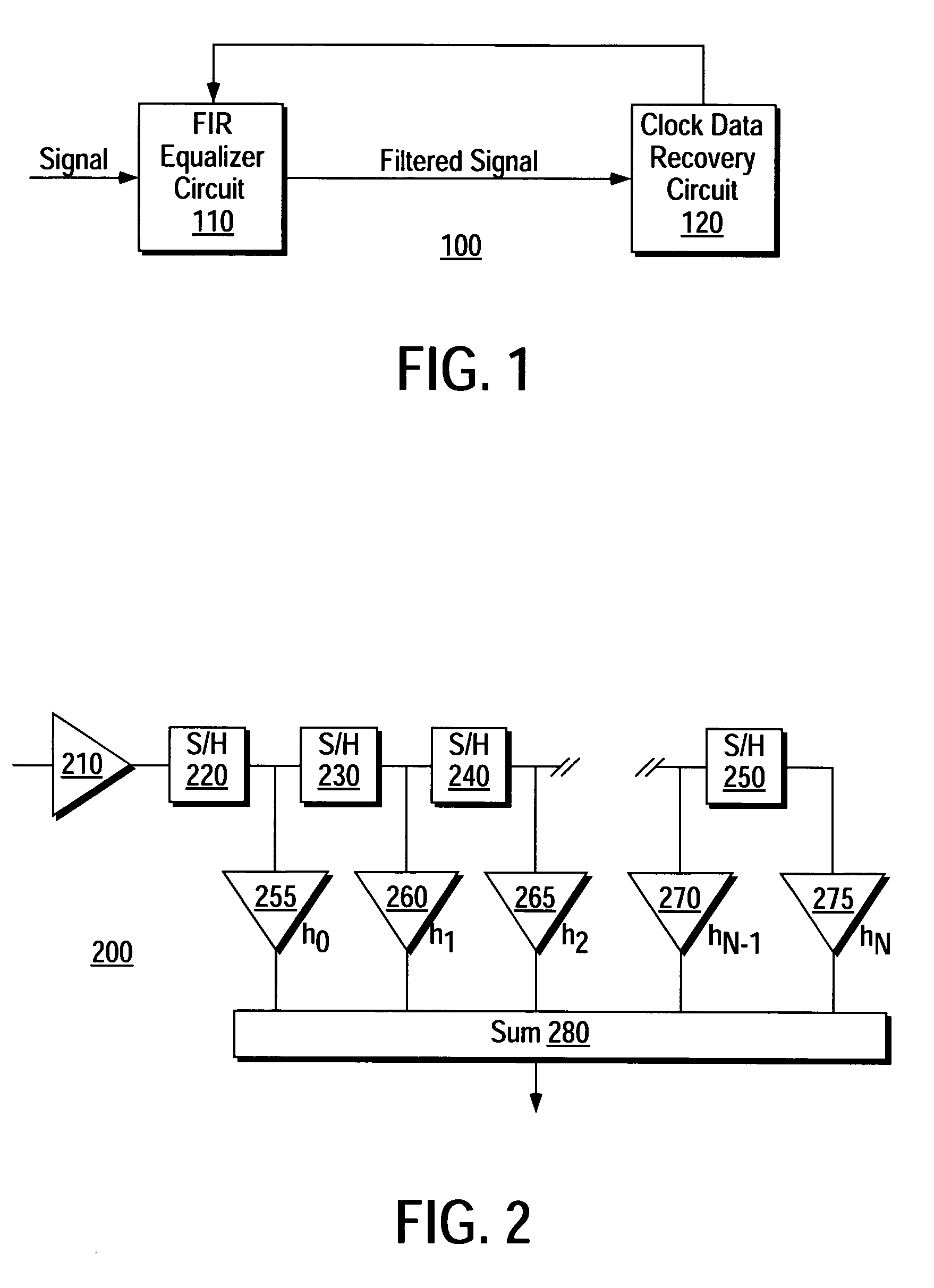
[0026]One application for a FIR equalizer circuit is for use in conjunction with a clock data recovery circuit. FIG. 1 is a block diagram illustrating one embodiment of a FIR equalizer and clock data recovery circuits. As shown in FIG. 1, a signal, such as a serial data stream, is input to a FIR equalizer circuit 110. In turn, the FIR equalizer circuit 110 filters or conditions the signal, in accordance with a predetermined impulse response function, for input to clock data recovery circuit 120.

[0027]In general, clock data recovery circuits recover the data at the receiver without receiving the sampling clock from the transmitter (i.e., a separate clock is generated at the receiver). Most clock data recovery circuits “over sample” the data to recover clock and data. In one over sampling method, the incoming data is first sampled at the bit cycle transition point to determine whether the phase of the clock at the receiver leads or lags the phase of the bit transitions in the serial b...


PUM


Abstract

An analog finite impulse response (“FIR”) filter generates a continuous time output using a chain of tunable delay elements. The tunable delay elements generate a time delay in an input signal. A calibration circuit, consisting of a control loop, tunes the delay elements to provide precision in the time delay response of the delay elements. The control loop generates a delay adjustment, based on the period of reference signals, and the phase adjustment is used to tune the parameters of the delay elements. The tunable delay elements may comprise any combination of transmission lines, lumped elements and semi-lumped elements.

Description

BACKGROUND OF THE INVENTION[0001]1. Field of the Invention[0002]The present invention is directed toward the field of electronic circuits, and more particularly toward a high-speed finite impulse response (“FIR”) equalizer.[0003]2. Art Background[0004]Data communication systems transport data at speeds defined by a predetermined data rate. The speed of transmitting data in modem broadband communication systems has rapidly increased in recent years. Today, data rates as high as 40 gigabits per second (“Gbps”) are required, as exemplified by the OC-768 optical networking standard.[0005]Some data communication systems utilize serial data transmission. For example, electronic circuits utilize serial data transmission to transmit data among one or more circuits. In general, serial data transmission involves transmitting bits in a single bit stream at a predetermined data rate. The data rate is expressed as the number of bits transmitted per second (“bps”). Typically, to transfer data bet...

Claims


Application Information

Patent Timeline
Patent Type & Authority Patents(United States)
IPC IPC(8): H03B1/00H03K5/00H04B1/10
CPCH03H15/02H03L7/0805H03L7/0812H03L7/0814H04L7/0037H04L25/03038H04L25/03133H04L25/03248H04L7/0029H04L2025/03477H03L7/0816
Inventor THON, LARS ERIK
Owner AVAGO TECH INT SALES PTE LTD
Why Eureka
Try Eureka