
Low cost multi-beam, multi-band and multi-diversity antenna systems and methods for wireless communications

a multi-band, multi-diversity, low-cost technology, applied in the direction of resonant antennas, polarised antenna unit combinations, different interaction antenna combinations, etc., can solve the problems of no low cost, prior art failure to provide an economical antenna system, and high cost of typical existing wireless communication antennas capable of providing adaptive beam forming and/or multiple beam switching, etc., to facilitate multi-band communication, improve communication or other services performance, and low cost

Active Publication Date: 2006-07-11
HONG KONG APPLIED SCI & TECH RES INST
View PDF16 Cites 246 Cited by
  • Summary
  • Abstract
  • Description
  • Claims
  • Application Information

AI Technical Summary

Benefits of technology

This solution enables the formation of multiple beams with flexible beam directions and shapes, supports multi-band communications, and provides enhanced performance for wireless communication systems with reduced noise and manufacturing costs, while maintaining high bandwidth and diversity capabilities.

Problems solved by technology

Typical existing wireless communication antennas capable of providing adaptive beam forming and / or multiple beam switching are relatively expensive.
No low cost antenna solution provides multiple beams along with antenna diversity, particularly an antenna that would further provide multiple bands and / or multiple services.
Thus, the prior art fails to provide an economical antenna system that has variable beams, reconfigurable for different beam patterns or an economical antenna system that provides communication via multiple bands using multiple services.
Existing, so called, adaptive antenna arrays, use components which render the cost of the system very high.
This dramatically increases the cost and complexity of the entire system.

Method used


Image

  • Low cost multi-beam, multi-band and multi-diversity antenna systems and methods for wireless communications
  • Low cost multi-beam, multi-band and multi-diversity antenna systems and methods for wireless communications
  • Low cost multi-beam, multi-band and multi-diversity antenna systems and methods for wireless communications

Examples


Embodiment Construction

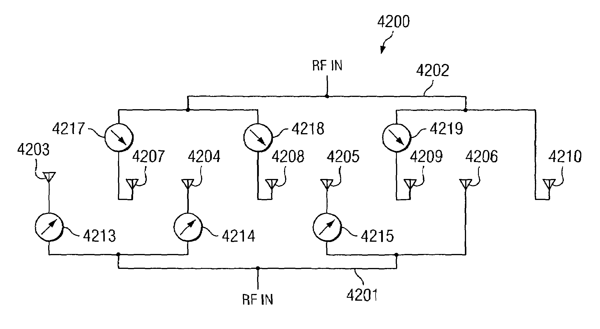
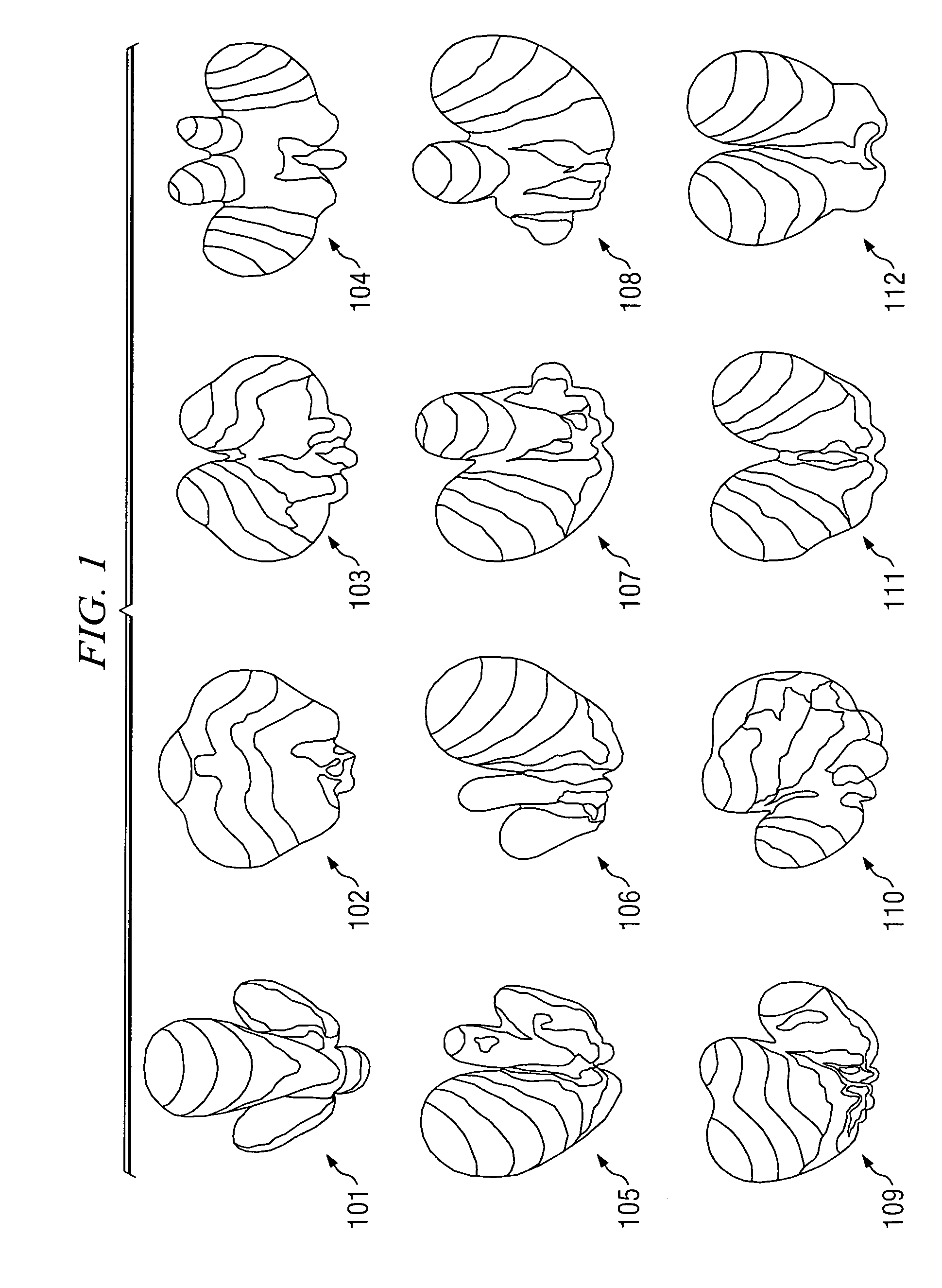
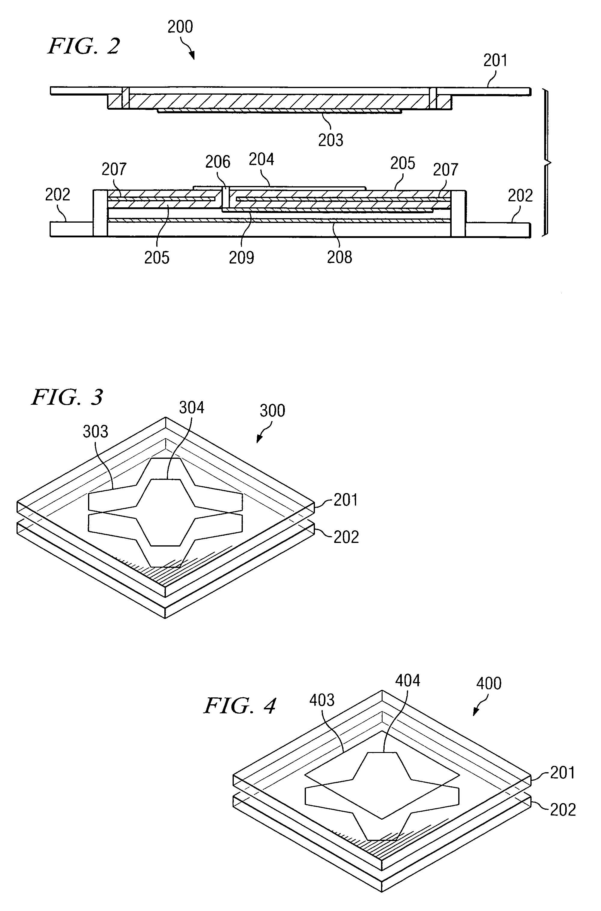
[0069]Various embodiments of the present systems and method may be used to form multiple beams simultaneously in different directions and / or with different attributes or characteristics, such as beam width, polarizations, or the like, using low cost panels. Embodiments of the present systems and methods provide different manners for reducing costs and providing solutions by varying the feed network employed. The present systems and methods may make use of inexpensive PIN or varactor diodes while maintaining performance and operating in multiple bands. In accordance with embodiments of the present systems and methods an array can employ closely packed, interleaved elements without sacrificing the radiation pattern resulting in a thin, compact array. The array may be further reduced in size through the use of switched phase shifters, eliminating the need for a bulky butler matrix. Multiple operating bands having the same aperture may result from interleaving elements for the various b...


PUM


Abstract

Systems and methods for employing switched phase shifters and a feed network to provide a low cost multiple beam antenna system for wireless communications. The present systems and methods may also facilitate multi-band communications and employ multi-diversity. The present systems and methods allow communication systems to achieve enhanced performance for communication or other services such as location tracking. The present systems and methods may employ switched phase shifters, multiple diversity antennas and / or a feed network having a multi-layer construction to provide an antenna system with low losses, low external component count and / or which is thin and compact.

Description

CROSS-REFERENCE TO RELATED APPLICATIONS[0001]The present invention is related to co-pending and commonly assigned U.S. patent application Ser. No. 10 / 278,062, entitled “DYNAMIC ALLOCATION OF CHANNELS IN A WIRELESS NETWORK”, filed Dec. 16, 2002; Ser. No. 10 / 274,834, entitled “SYSTEMS AND METHODS FOR MANAGING WIRELESS COMMUNICATIONS USING LINK SPACE INFORMATION”, filed Jan. 2, 2003; Ser. No. 10 / 348,843, entitled “WIRELESS LOCAL AREA NETWORK TIME DIVISION DUPLEX RELAY SYSTEM WITH HIGH SPEED AUTOMATIC UP-LINK AND DOWN-LINK DETECTION”, filed Jan. 2, 2003; Ser. No. 10 / 677,418, entitled “SYSTEM AND METHOD FOR PROVIDING MULTIMEDIA WIRELESS MESSAGES ACROSS A BROAD RANGE AND DIVERSITY OF NETWORKS AND USER TERMINAL DISPLAY EQUIPMENT”, filed Oct. 2, 2003; and Ser. No. 10 / 635,367, entitled “LOCATION POSITIONING IN WIRELESS NETWORKS”, filed Aug. 6, 2003; the disclosures of which are incorporated herein by reference.TECHNICAL FIELD[0002]The present invention is generally related to wireless commun...

Claims


Application Information

Patent Timeline
Patent Type & Authority Patents(United States)
IPC IPC(8): H01Q1/38H01Q21/00H01Q1/24H01Q21/24H01Q21/28H01Q21/29H01Q25/00
CPCH01Q1/246H01Q21/24H01Q25/005H01Q21/29H01Q25/00H01Q21/28
Inventor SONG, PETER CHUN TECKMURCH, ROSS DAVIDKEUNG, ANGUS MAK CHIGEORGE, DOUGLAS RONALDWONG, PIU BILL
Owner HONG KONG APPLIED SCI & TECH RES INST
Learn More