Fan-beam antenna

a technology of fan beam and antenna, which is applied in the direction of antennas, subaqueous/subterranean adaption, radiating element housings, etc., can solve the problems of difficult method of manufacturing compound materials, large thickness of lens, and large size in propagation direction, so as to achieve the necessary lens effect and restrain bad reflection

Inactive Publication Date: 2006-07-11
TAIYO MUSEN
View PDF6 Cites 200 Cited by
  • Summary
  • Abstract
  • Description
  • Claims
  • Application Information

AI Technical Summary

Benefits of technology

[0013]An object of the present invention is to provide a high-gain fan-beam antenna whose cross-sectional shape is thin by easily constituting a dielectric lens with little reflection in order to resolve the above mentioned problems.
[0019]Therefore, according to the present invention, even if a convenience of a simple extrusion molding or an injection molding is considered, bad reflection can be restrained and a necessary lens effect is gained easily, so that a compact and high-gain fan-beam antenna can be easily obtained.

Problems solved by technology

In an example disclosed in JP 60-261204 A or JP 62-171301 A, there is a disadvantage such that a size in a propagation direction becomes larger though a vertical size can be restrained in a method for projecting the above mentioned dielectric plate with a few wavelengths.
Thus, it can be supposed easily that a thickness of the lens becomes larger, and further problems arise in a forming or a means for securing.
Moreover, as shown in FIGS. 7 and 8, if a dielectric constant in a center portion can be larger, a thickness of the lens can be thinner, but a method for manufacturing compound materials is difficult, so that these methods are rarely used in a fan-beam antenna.

Method used


Image

  • Fan-beam antenna
  • Fan-beam antenna
  • Fan-beam antenna

Examples


first embodiment

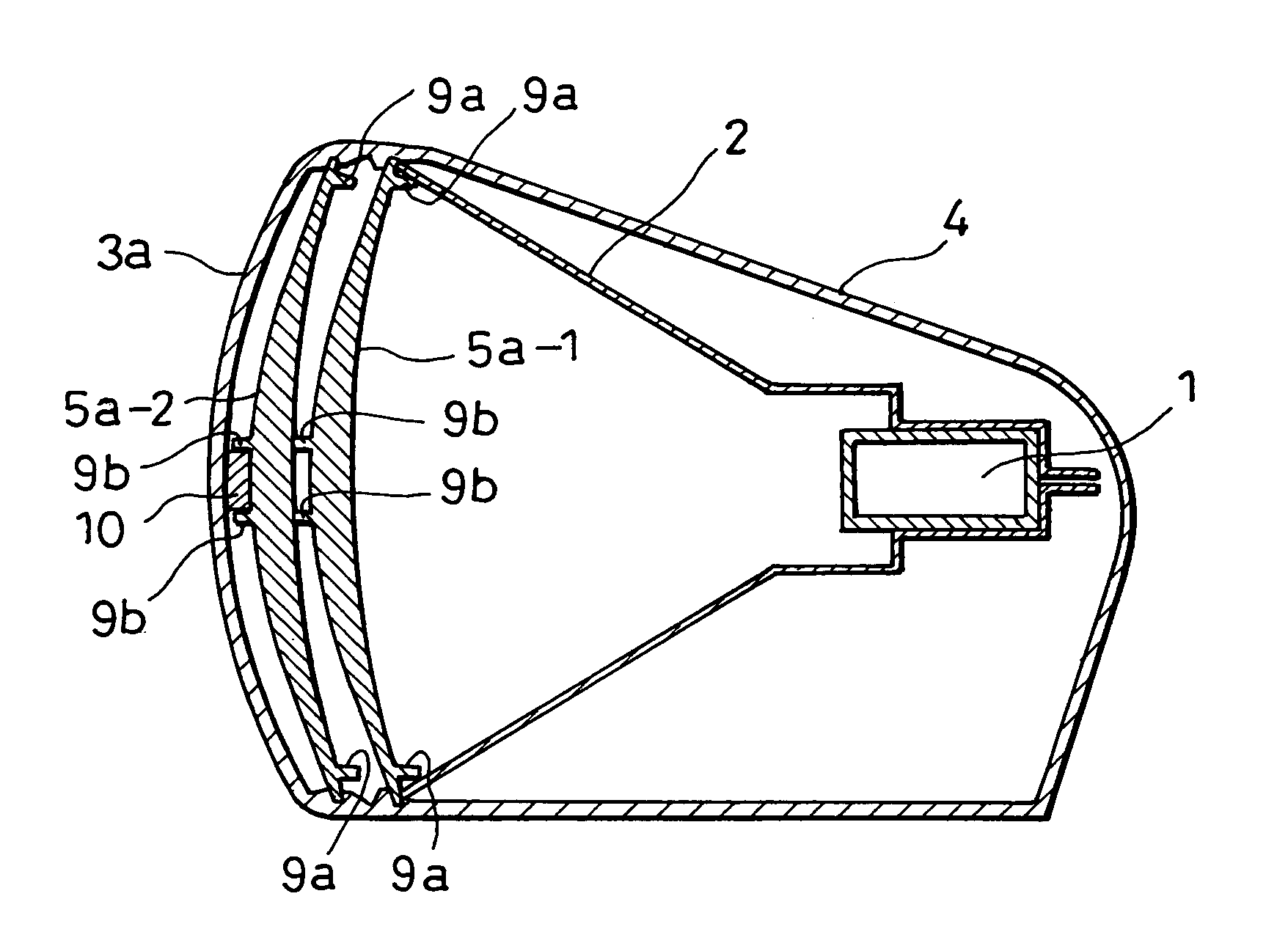
[0031]A cross section view illustrating a fan-beam antenna according to the present invention is shown in FIG. 1.

[0032]A fan beam antenna shown in FIG. 1 is an example in which a slot waveguide (1) is employed as an array element, wherein two convex-lens-shaped dielectric lenses (5a-1, 5a-2) and radiation surface radome (3a) formed by a dielectric with an even thickness are arranged in an opening portion of a flare (2) and the other portions are covered with a water-proof box (4). Note that mechanical support means for the slot waveguide and the flare, and a feeder system etc. are omitted in the drawing.

[0033]Besides, in this embodiment, the radiation surface radome (3a) and the water-proof box (4) are united and formed by a cylindrical extrusion molding. Furthermore, the dielectric lenses (5a-1, 5a-2) are approximately the same shape and formed by an extrusion molding or an injection molding, having a structure to be fit into the water-proof box (4).

[0034]Moreover, in this embodime...

second embodiment

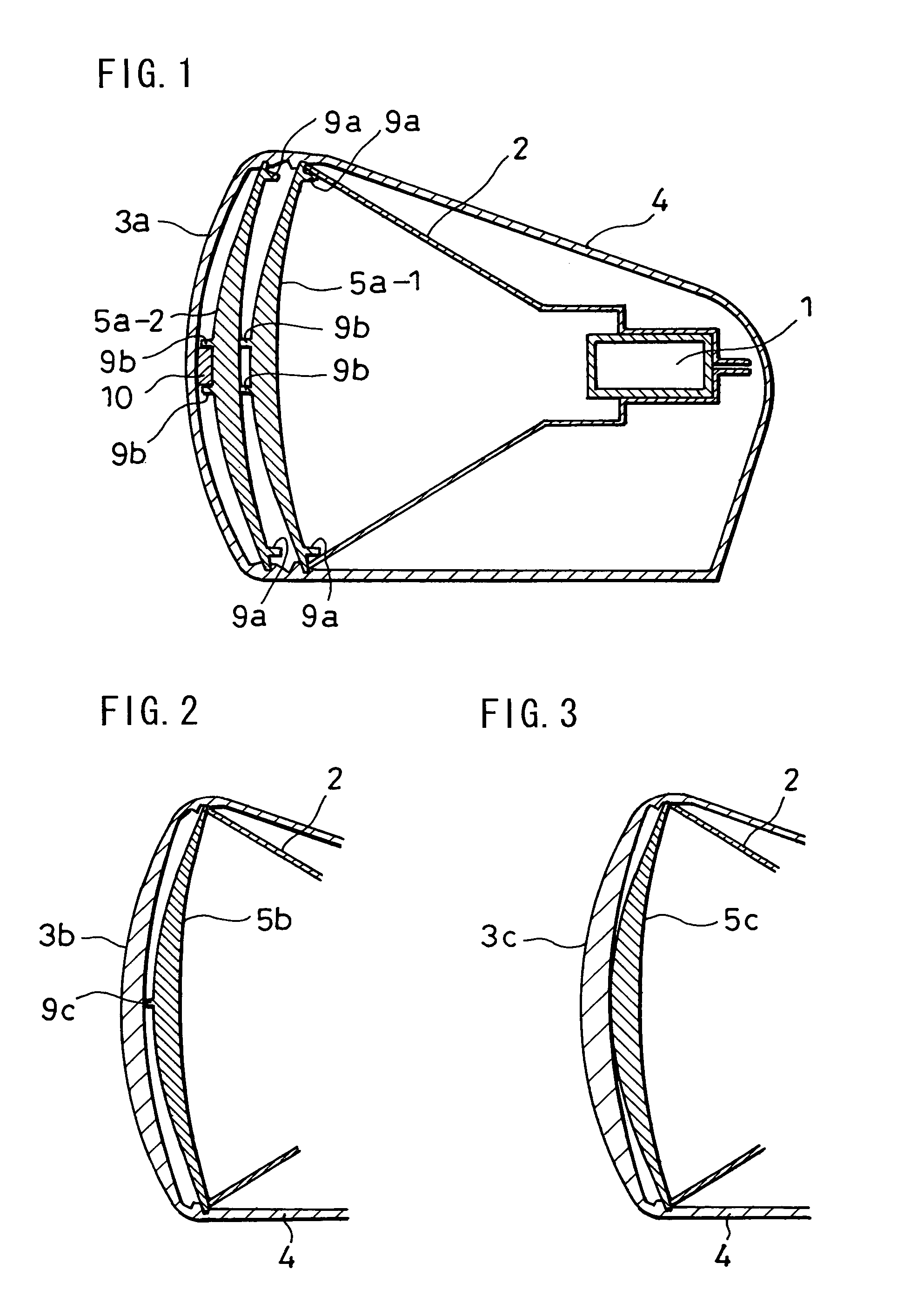
[0056]FIGS. 2, 3 and 4 illustrate cross sectional views of a fan-beam antenna according to the present invention.

[0057]FIG. 2 shows an example in which a radome itself is a convex-shaped dielectric lens (3b) and a dielectric lens (5b) which is similar to the dielectric lens (3b) is located inside thereof, a thickness of a center of each lens is set to an electric length equal to or less than a quarter wavelength of a used frequency, and pitch between two lenses over a whole of the vertical surface is set to a quarter wavelength of the electric length.

[0058]With this arrangement, an excellent effect for restraining reflection can be gained in a principle such that two same waves which are separated at intervals of a quarter wave length in an advanced direction thereof are negated. Note that the dielectric lens (5b) in FIG. 2 is provided with a spacer projection (9c) at a center thereof.

[0059]FIG. 3 shows an example in which a radome itself is a convex-shaped dielectric lens (3c) and ...

third embodiment

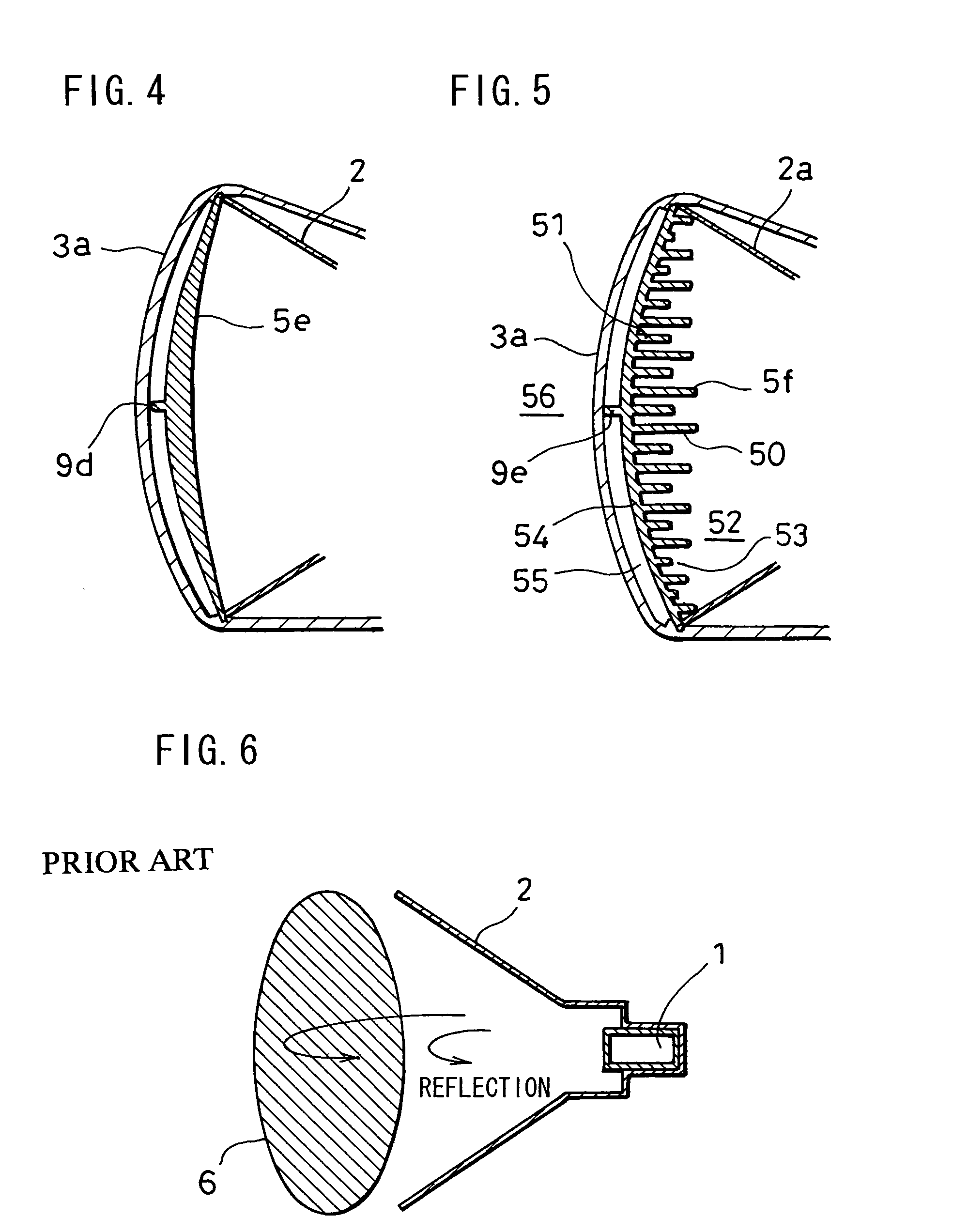
[0064]FIG. 5 illustrates a cross sectional view of a fan-beam antenna according to the present invention. In the embodiment in FIG. 5, a point such that a dielectric lens (5f) is formed so as to have a comb-shaped cross section is different from the above embodiments. In this case, this embodiment is such that reflection is restrained by a structure as follows such as to apply an average dielectric constant by gaps (53) between comb tooth portions (50, 51) and a space (52) to gain a desired lens effect.

[0065]Note that the dielectric lens (5f) in FIG. 5 is provided with a spacer projection (9e) at a center thereof.

[0066]A portion where density of teeth (50, 51) is the highest: it is a portion which is a dielectric lens (5f) and a maximum thickness (length of comb tooth (50)) is set voluntarily by a necessary lens effect.

[0067]A portion where density of inside teeth (51) is lower: where an average relative dielectric constant is set so as to be a square root of the relative dielectric...


PUM


Abstract

An object of the invention is to provide a fan-beam antenna which comprises a flare which is long in a horizontal direction thereof and whose cross section is horn-shaped, and a water-proof box housing components of said antenna, in which a vertical beam width is made narrow without spreading a vertical size to increase gain. Accordingly, this invention is characterized in that a radome radiation surface is constituted of a plurality of dielectric plates equivalently, and at least one of the dielectric plates is made a dielectric lens having a characteristic similar to a convex lens.

Description

BACKGROUND OF THE INVENTION[0001]The present invention relates to a fan-beam antenna which is used in a radar system etc. and in which a level surface beam width is made narrow and a vertical surface beam width is made wide, and further in which dielectric lenses are used together for an antenna in which a vertical surface directivity is restricted by a horn-shaped flare.[0002]In a radar system detecting a target by scanning a directivity antenna over a whole circumference or in a specific sector, an array antenna is provided with a flare such as a slot array antenna in which radiation elements are arranged in a horizontal direction to reduce the horizontal surface beam width and to restrict a vertical surface beam width easily by the horn-shaped flare in a vertical direction.[0003]Proposals such that a gain is secured while restraining an opening of the flare to a practical size by such array antenna with a flare, for instance an S-band radar for shipping, namely such that a vertic...

Claims


Application Information

Patent Timeline
Patent Type & Authority Patents(United States)
IPC IPC(8): H01Q19/06H01Q13/00H01Q15/08H01Q1/04H01Q1/42H01Q13/02H01Q19/08
CPCH01Q1/42H01Q19/08H01Q13/02H01Q1/04
Inventor HIDAI, TAKASHIONO, KAZUYOSHI
Owner TAIYO MUSEN
Why Eureka
Try Eureka