

Short range radio communication system with using improved authentication scheme
- Summary
- Abstract
- Description
- Claims
- Application Information
AI Technical Summary
Benefits of technology
Problems solved by technology
Method used
Image

Examples
first embodiment
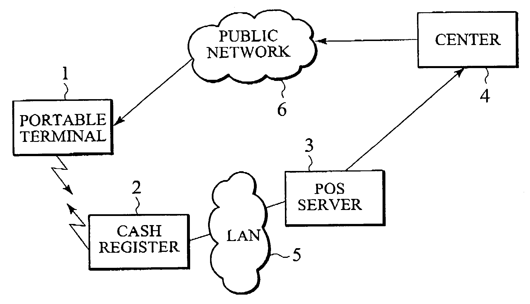
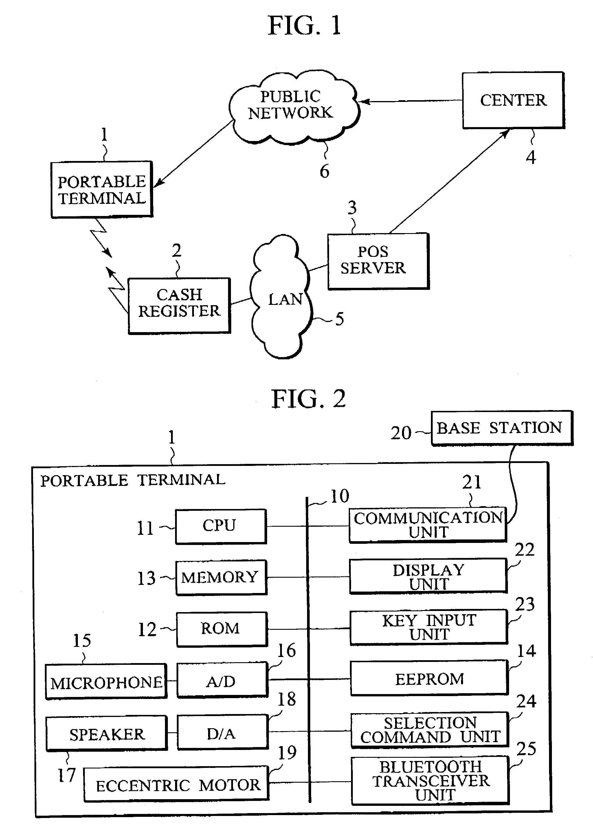
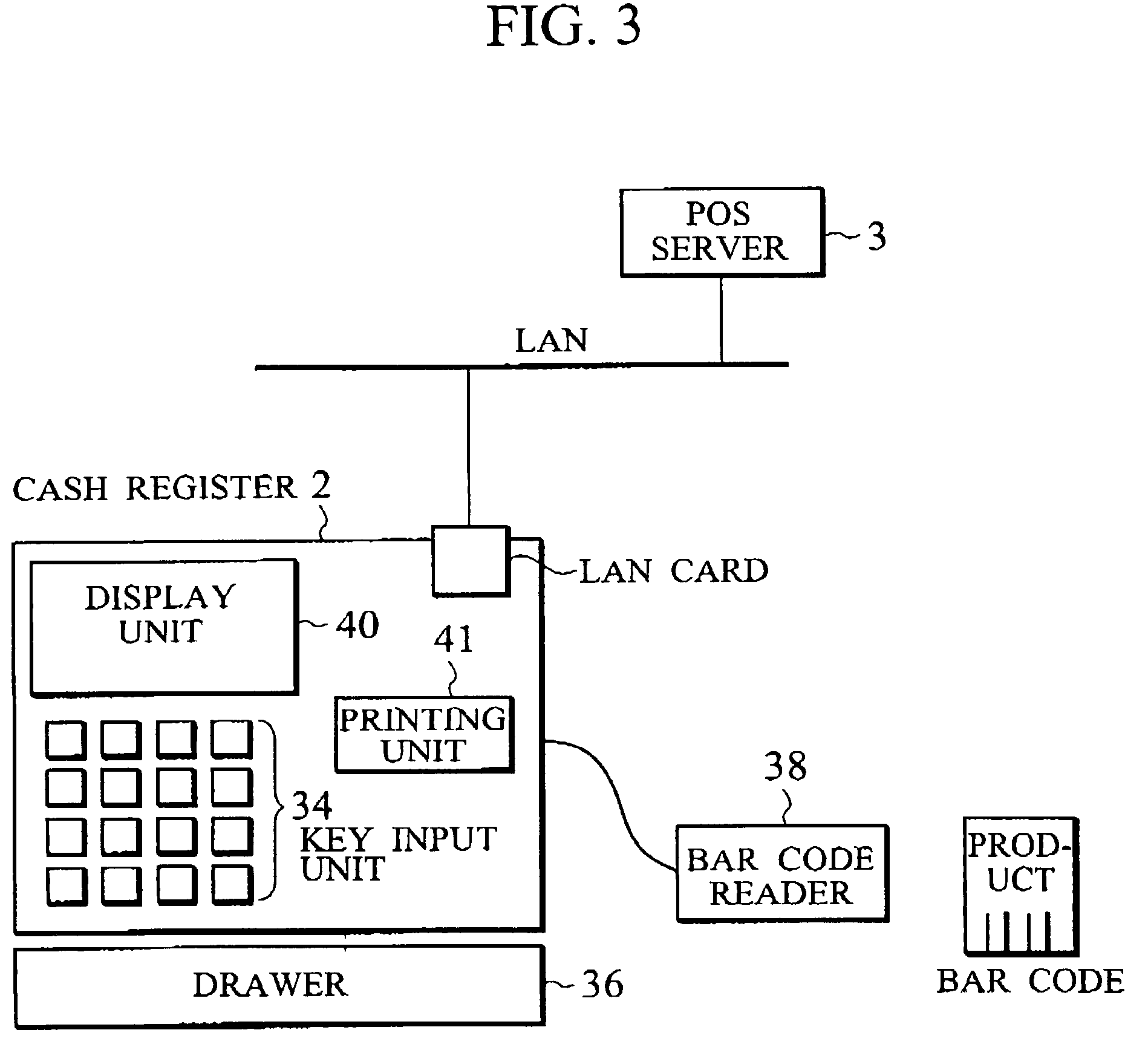
[0050]FIG. 1 shows a schematic configuration of a communication system according to the first embodiment of the present invention, in an exemplary form of a POS (Point Of Sales) system. The communication system of FIG. 1 has a portable terminal 1 owned by a customer, a cash register 2 for carrying out short range radio communications with this portable terminal 1, a POS server 3 for managing information on sales made by the cash register 2, and a center 4 for providing various services to each customer.
[0051]The cash register 2 and the POS server 3 are connected through a LAN 5, the POS server 3 and the center 4 are connected through a public network (or dedicated line) 6, and the center 4 and the portable terminal 1 owned by each customer are connected through a public radio network. The portable terminal 1 and the cash register 2 carry out communications according to the specification of the Bluetooth, for example.
[0052]The POS server 3 manages the sold product names, sold prices,...
second embodiment
[0134]In contrast to the first embodiment in which the PIN code is generated at the portable terminal 1, the second embodiment is directed to the case of generating the PIN code at the cash register 2.
[0135]FIG. 9 shows an exemplary processing operation of the portable terminal 1 in the second embodiment, and FIG. 10 shows an exemplary processing operation of the cash register 2 in the second embodiment. The flow charts of FIG. 9 and FIG. 10 contain many overlaps with the flow charts of FIG. 6 and FIG. 7, so that the differences will be mainly described in the following.
[0136]The user who makes the payment at the cash register 2 takes out the portable terminal 1 and activates an application for receiving services. This application initializes the BT transceiver unit 25 (step S81).
[0137]Then, in order to search the cash register 2 with the BT transceiver unit 39 that can be connected to the BT transceiver unit 25, the issuance of a restricted inquiry command is requested to the BT tr...
third embodiment
[0146]In contrast to the first and second embodiments in which the link authentication function of the Bluetooth is utilized, the third embodiment is directed to the case of not utilizing the link authentication function.
[0147]FIG. 11 shows an exemplary processing operation of the portable terminal 1 in the third embodiment.
[0148]The user who makes the payment at the cash register 2 takes out the portable terminal 1 and activates an application for receiving services. This application initializes the BT transceiver unit 25 (step S141).
[0149]The application presents a part or a whole of the identifier of the portable terminal 1 at the display unit 22 (step S142). At the same time, in order to search the cash register 2 with the BT transceiver unit 39 that is connectable, the issuance of a restricted inquiry command is requested to the BT transceiver unit 25, and the BT transceiver unit 25 transmits the restricted inquiry command for a prescribed period of time (step S143). At this po...
PUM
 Abstract
Description
Claims
Application Information