
System and method for performing rapid control prototyping using a plurality of graphical programs that share a single graphical user interface

a technology of graphical programs and user interfaces, applied in the field of graphical programming, can solve the problems of limiting the achievement of optimal utilization of computer systems, user programming skills and ability to interact with the computer system, and the task of programming a computer system to model or implement a process is often further complicated, etc., to speed up the product development process, perform significantly easier and more quickly, and quickly and easily test

Inactive Publication Date: 2006-07-11
NATIONAL INSTRUMENTS
View PDF7 Cites 69 Cited by
  • Summary
  • Abstract
  • Description
  • Claims
  • Application Information

AI Technical Summary

Benefits of technology

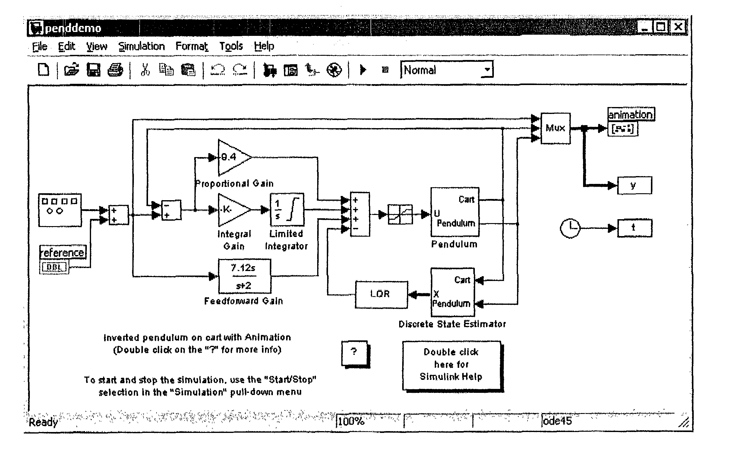
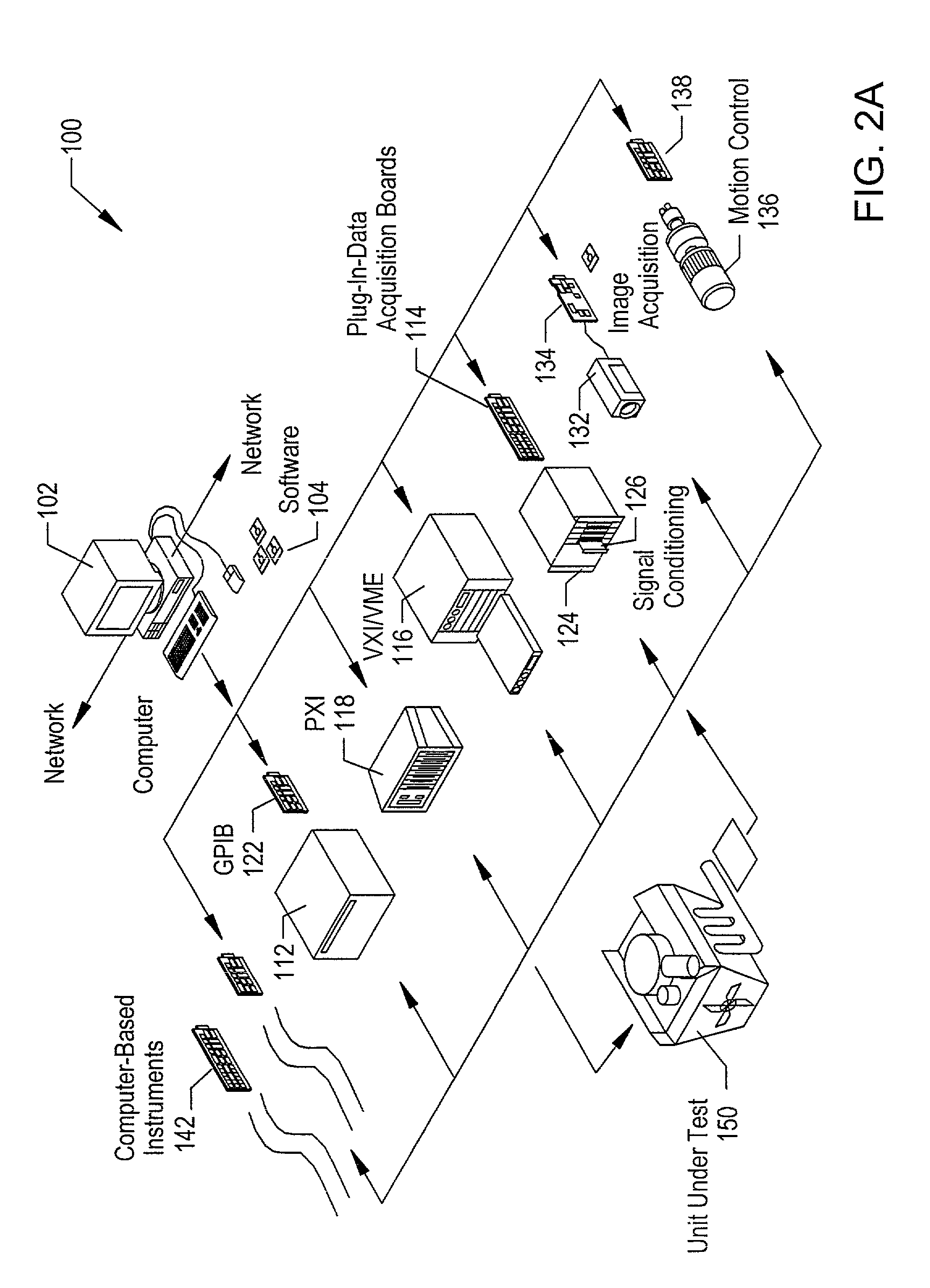
[0019]The target controller or device that executes the control algorithm under test may be coupled to a real physical system, i.e., the physical system that the production device will be used to control. Thus, the target device executing the control algorithm may behave much the same as if the production device were controlling the physical system. However, the process of deploying a control algorithm on the target device may be performed significantly easier and more quickly than if a production device were manufactured to test each version of a control algorithm under test. For example, the programming environment used to create the control algorithm may provide support for automatically deploying the algorithm on the target device. Thus, the design / test process may be a very tight closed loop, allowing designs to be quickly and easily tested and significantly speeding up the product development process.

Problems solved by technology

When traditional text-based programming environments are used, the user's programming skills and ability to interact with the computer system often become a limiting factor in the achievement of optimal utilization of the computer system.
There are numerous subtle complexities which a user must master before he can efficiently program a computer system in a text-based environment.
The task of programming a computer system to model or implement a process often is further complicated by the fact that a sequence of mathematical formulas, mathematical steps or other procedures customarily used to conceptually model a process often does not closely correspond to the traditional text-based programming techniques used to program a computer system to model such a process.
Since a user often is not fully proficient in techniques for programming a computer system in a text-based environment to implement his solution, the efficiency with which the computer system can be utilized often is reduced.
Traditional users of these systems, however, often were not highly trained in programming techniques and, in addition, text-based programming languages were not sufficiently intuitive to allow users to use these languages without training.
Therefore, implementation of such systems frequently required the involvement of a programmer to write software for control and analysis of instrumentation or industrial automation data.
Thus, development and maintenance of the software elements in these systems often proved to be difficult.
Alternatively, the front panel may be used merely to view the input and output, or just the output, and the input may not be interactively manipulable by the user during program execution.
However, in general, prior art systems do not provide the capability for separate graphical programs to share the same graphical user interface.

Method used


Image

  • System and method for performing rapid control prototyping using a plurality of graphical programs that share a single graphical user interface
  • System and method for performing rapid control prototyping using a plurality of graphical programs that share a single graphical user interface
  • System and method for performing rapid control prototyping using a plurality of graphical programs that share a single graphical user interface

Examples


Embodiment Construction

Incorporation by Reference

[0045]The following references are hereby incorporated by reference in their entirety as though fully and completely set forth herein.

[0046]U.S. Pat. No. 6,064,812 titled “System and Method for Developing Automation Clients Using a Graphical Data Flow Program,” issued on May 16, 2000.

[0047]U.S. Pat. No. 6,102,965 titled “System and Method for Providing Client / Server Access to Graphical Programs,” issued on Aug. 15, 2000.

[0048]U.S. Pat. No. 6,173,438 titled “Embedded Graphical Programming System” filed Aug. 18, 1997.

[0049]U.S. Pat. No. 6,219,628 titled “System and Method for Configuring an Instrument to Perform Measurement Functions Utilizing Conversion of Graphical Programs into Hardware Implementations,” filed Aug. 18, 1997.

[0050]U.S. patent application Ser. No. 09 / 136,123 titled “System and Method for Accessing Object Capabilities in a Graphical Program,” filed Aug. 18, 1998.

[0051]U.S. patent application Ser. No. 09 / 518,492 titled “System and Method for P...


PUM


Abstract

A system and method for performing rapid control prototyping using a plurality of graphical programs that share a single graphical user interface. A first graphical program may be created that models a product being designed. The first graphical program may be deployed on a target device for execution. A second graphical program that performs a measurement function may be created. The target device may be coupled to a physical system. The first graphical program may be executed on the target device to simulate operation of the product. The second graphical program may be executed to measure characteristics of the operation of the physical system and / or characteristics of the operation of the product. A single graphical user interface comprising a first one or more graphical user interface elements for the first graphical program and a second one or more graphical user interface elements for the second graphical program may be displayed.

Description

FIELD OF THE INVENTION[0001]The present invention relates to the field of graphical programming. In particular, the invention relates to a system and method for performing rapid control prototyping using a plurality of graphical programs that share a single graphical user interface.DESCRIPTION OF THE RELATED ART[0002]Traditionally, high level text-based programming languages have been used by programmers in writing application programs. Many different high level programming languages exist, including BASIC, C, Java, FORTRAN, Pascal, COBOL, ADA, APL, etc. Programs written in these high level languages are translated to the machine language level by translators known as compilers or interpreters. The high level programming languages in this level, as well as the assembly language level, are referred to herein as text-based programming environments.[0003]Increasingly, computers are required to be used and programmed by those who are not highly trained in computer programming techniques...

Claims


Application Information

Patent Timeline
IPC IPC(8): G09G5/00G06F9/44G06F17/50
CPCG06F8/34G06F17/5009Y10S715/97G06F2217/86G06F2117/08G06F30/20G09G5/00
Inventor SANTORI, MIKELIMROTH, JOHN
Owner NATIONAL INSTRUMENTS
Learn More