Hydraulic circuit of construction machinery

a technology of construction machinery and hydraulic circuit, applied in the direction of positive displacement liquid engine, fluid coupling, servomotor, etc., can solve the problems of insufficient pressure oil feed to the revolving hydraulic motor, extreme unpleasantness of the operator, and slow revolving speed, so as to avoid an excessive drop in the speed of each actuator, reduce displacement, and improve operability

Inactive Publication Date: 2006-07-18
NIHON KENKI CO LTD
View PDF10 Cites 28 Cited by
  • Summary
  • Abstract
  • Description
  • Claims
  • Application Information

AI Technical Summary

Benefits of technology

[0014]The present invention, in a forth aspect thereof, features that limiting means for applying a predetermined limit to a delivery pressure signal from the third hydraulic pump is arranged on the third guide line. Owing to the arrangement of the limiting means, even when a load on the actuator fed with pressure oil from the third hydraulic pump increases, at least predetermined flow rates can be secured as delivery flow rates from the first and second hydraulic pumps without extremely decreasing the displacements of the first and second hydraulic pumps. It is, therefore, possible to avoid an excessive drop in the speed of each actuator and to assure good operability.

Problems solved by technology

According to this conventional technique, however, all the hydraulic pumps are designed to be controlled evenly, so that during such combined operation, the feed of pressure oil to the revolving hydraulic motor becomes insufficient and the revolving speed becomes slower.
During operation of a hydraulic excavator, variations especially in revolving speed make its operator feel extreme unpleasant.
As appreciated from the foregoing, no consideration is made to any particular actuator in this conventional technique, and therefore, a problem exists especially in operability.
When revolving drive is performed during operation of a boom, for example, the flow rate of pressure oil to be fed to the hydraulic cylinder for the boom extremely decreases, leading to a sudden slowdown in the operation speed of the boom.
As appreciated from the foregoing, the other conventional technique also involves an unsolved problem especially in operability.

Method used


Image

  • Hydraulic circuit of construction machinery
  • Hydraulic circuit of construction machinery
  • Hydraulic circuit of construction machinery

Examples


first embodiment

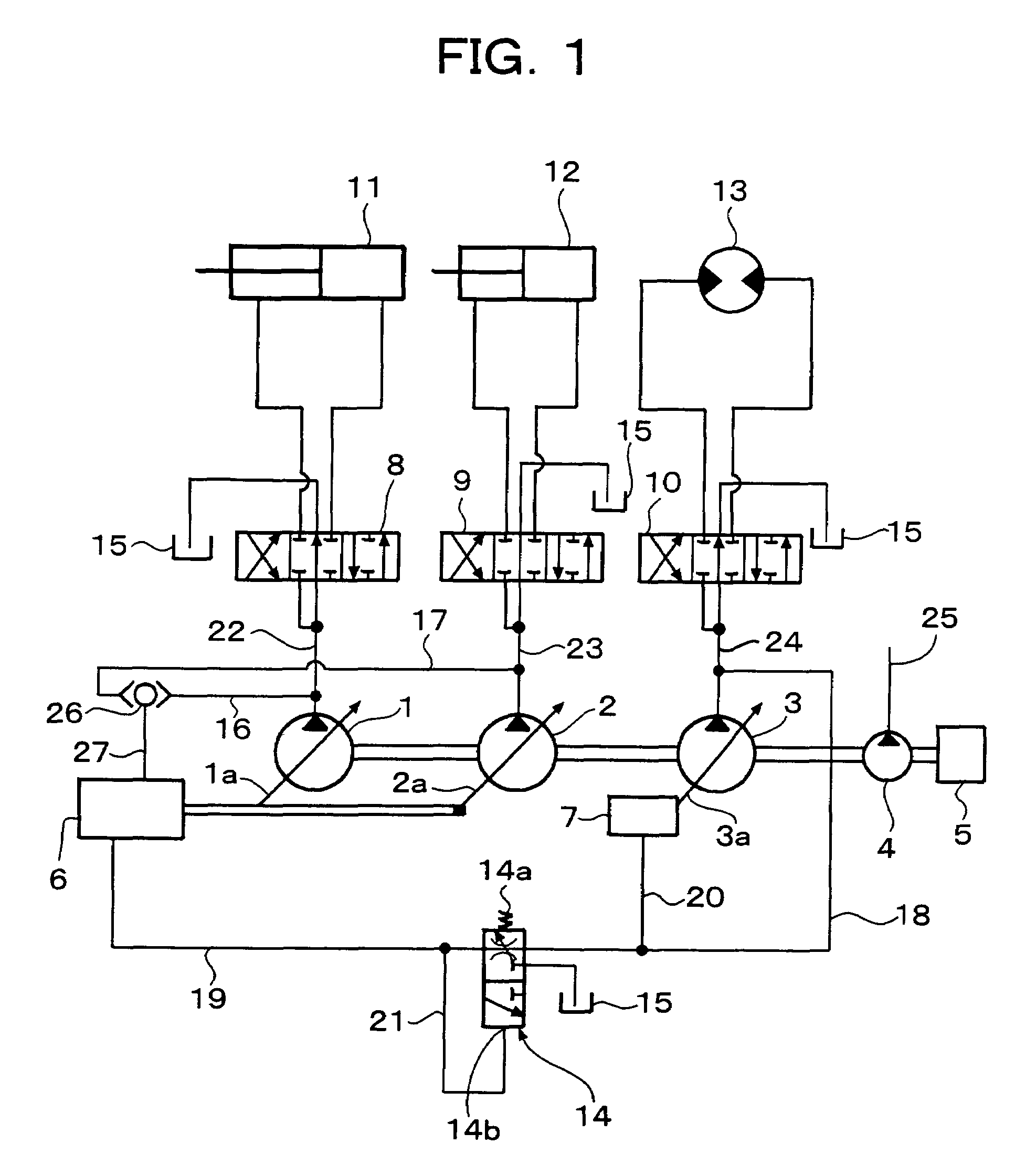
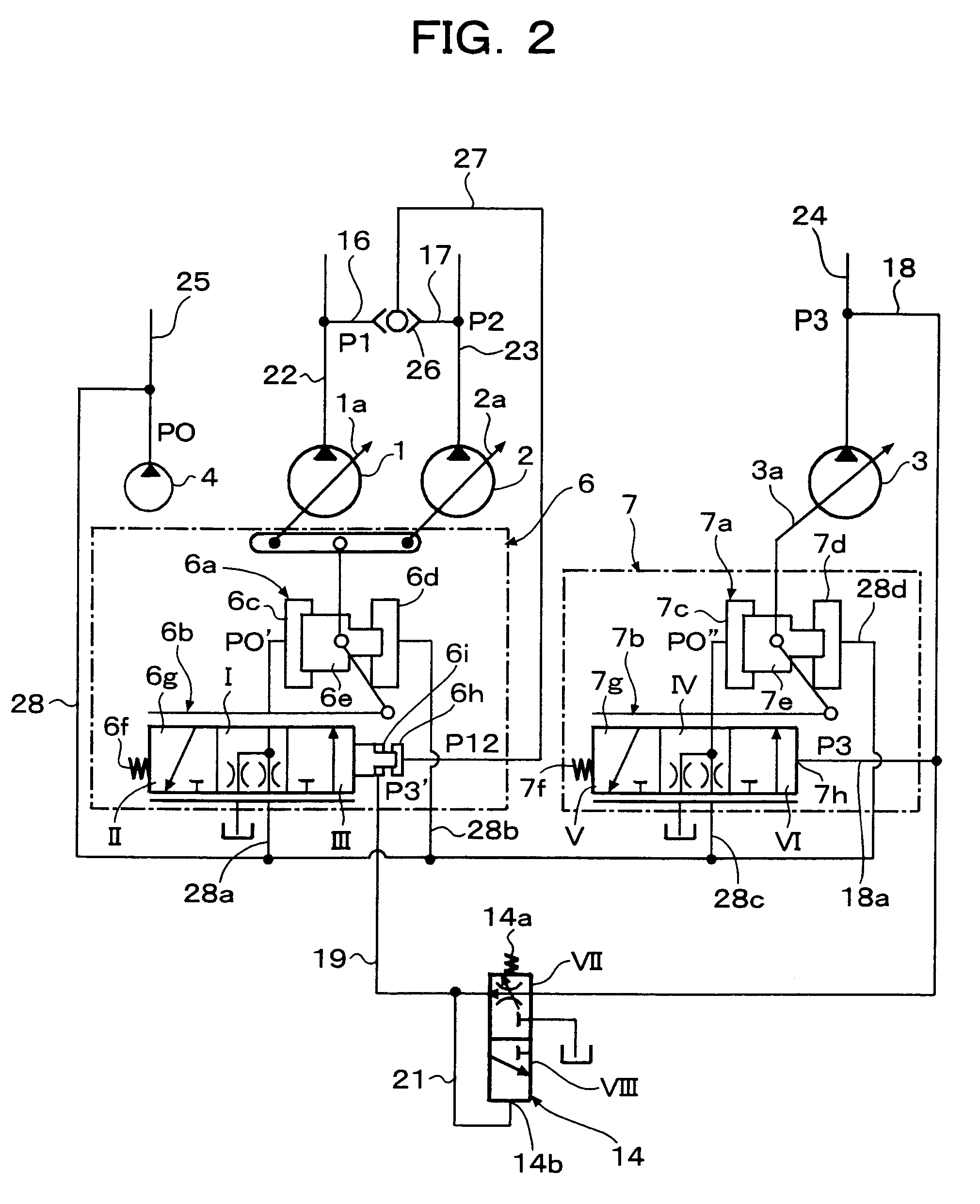
[0040]In this embodiment, the present invention is applied to a hydraulic circuit of a hydraulic excavator as a construction machine. FIG. 1 through FIG. 5 illustrate the first embodiment, in which FIG. 1 is an entire hydraulic circuit diagram, FIG. 2 is a fragmentary hydraulic circuit diagram, FIG. 3 is a characteristic diagram of delivery flow rate of a third hydraulic pump, FIG. 4 is a characteristic diagram of delivery flow rates of a first and second hydraulic pumps, and FIG. 5 is an appearance view of the hydraulic excavator.

[0041]As illustrated in FIG. 5, the hydraulic excavator as the construction machine to which the present invention is applied is equipped with a travel base 41 which can travel by an unillustrated travel motor, a revolving superstructure 40 having an operator's cab 43 and an engine room 42 and revolvable by a revolving hydraulic motor 13 depicted in FIG. 1, and front members 47 constructed of a boom 44, arm 45 and bucket 46 which can be pivoted by hydrauli...

second embodiment

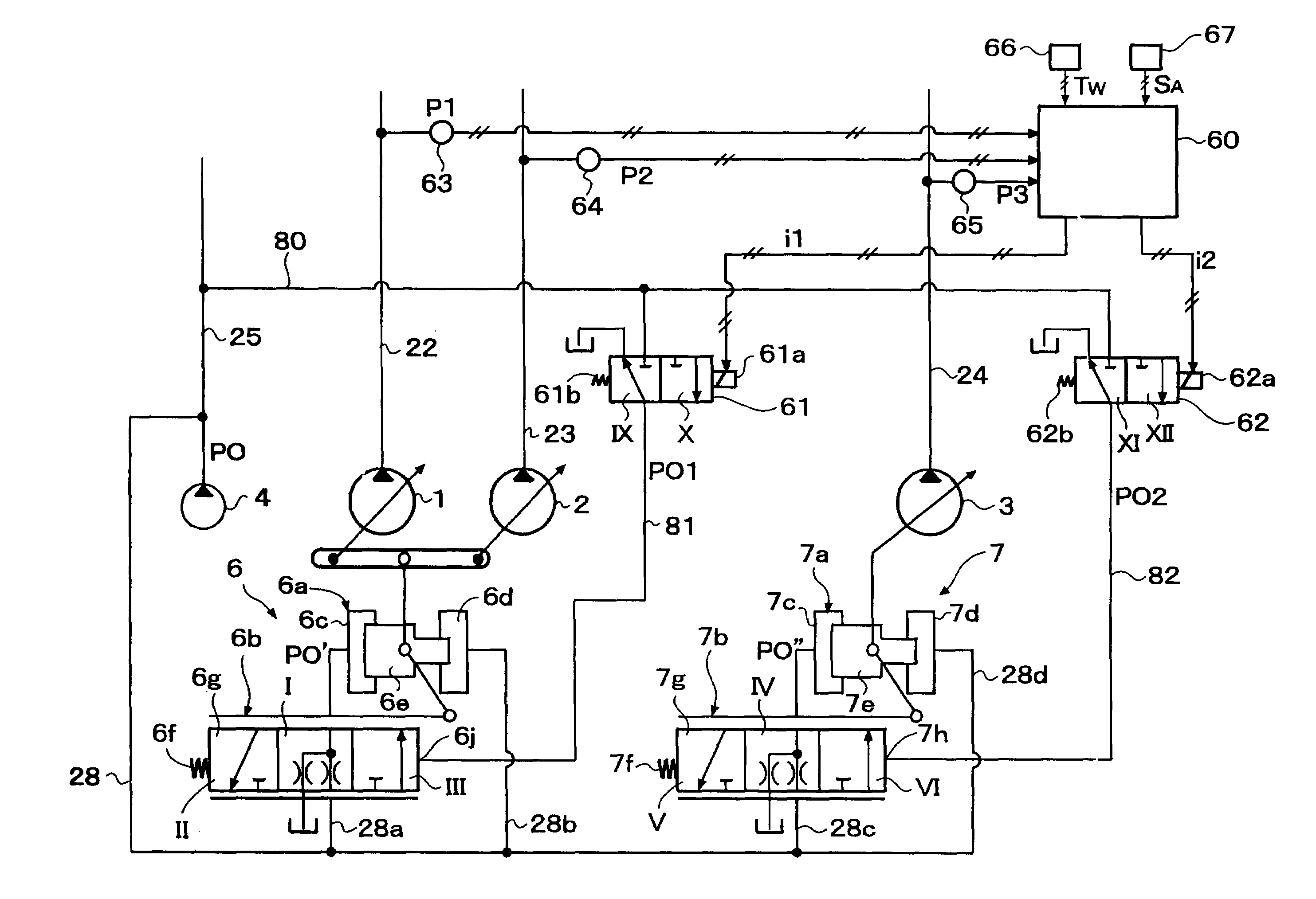
[0054]Referring next to FIG. 6 through FIG. 9, a description will be made about the second embodiment of the present invention. FIG. 6 is a fragmentary hydraulic circuit diagram in the second embodiment, FIG. 7 is a flow chart showing a flow of processing by a controller, FIG. 8 is a characteristic diagram of a delivery flow rates from a first and second hydraulic pumps, and FIG. 9 is a characteristic diagram of a flow rate from a third hydraulic pump. It is to be noted that those portions of the hydraulic circuit which are the same as the corresponding parts described above in connection with the first embodiment are shown by the same reference numerals and overlapping descriptions are omitted.

[0055]As shown in FIG. 6, this second embodiment is provided with a controller 60, which performs the below-mentioned computing processing based on signals inputted from pressure sensors 63, 64, 65 for detecting delivery pressures P1, P2, P3 of a first, second and third hydraulic pumps 1, 2, ...

third embodiment

[0068]Based on FIG. 10 and FIG. 11, a description will next be made about the third embodiment of the present invention. FIG. 10 is a diagram showing input-output correlations with respect to a controller 60A, and FIG. 11 is a map diagram for obtaining a correction coefficient upon performing processing at the controller 60A.

[0069]As shown in FIG. 10, the controller 60A in this third embodiment is inputted with delivery pressure signals P1, P2, P3 of the individual hydraulic pumps 1, 2, 3 and also with swing angle signals èBO, èA, èBU from the angle sensors 70, 71, 72 arranged on the boom 44, arm 45 and bucket 46, respectively, which make up the front members 47 of the hydraulic excavator illustrated in FIG. 5. The remaining construction is equivalent to the above-described second embodiment.

[0070]According to the third embodiment constructed as described above, the controller 60A calculates a horizontal distance L from the revolving superstructure 40 to a tip of the bucket 45 on th...


PUM


Abstract

To keep one of three hydraulic pumps unaffected by variations in torque of the remaining hydraulic pumps when the three hydraulic pumps are used, displacements of the first and second hydraulic pumps are controlled based on their own delivery pressures P1, P2 and a pressure P3′ obtained by reducing through a reducing valve 14 a delivery pressure P3 from the third hydraulic pump, while a displacement of the third hydraulic pump 3 is controlled only by its own delivery pressure P3. The pressure oil delivered from the third hydraulic pump 3, therefore, remains unaffected by variations in delivery flow rates from the first and second hydraulic pumps 1,2, in other words, by variations in their torque consumptions, so that the third hydraulic pump is assured to provide a stable flow rate.

Description

TECHNICAL FIELD[0001]This invention relates to a hydraulic circuit suited for arrangement in a construction machine such as a hydraulic excavator and having at least three hydraulic pumps drivable by an engine, especially to a hydraulic circuit capable of controlling displacements of the respective hydraulic pumps such that a torque consumed as a result of driving of the individual hydraulic pumps does not exceed output power force from the engine, and also to a construction machine equipped with the hydraulic circuit.BACKGROUND ART[0002]As a conventional technique of this kind, the invention disclosed in JP-A-53110102 is known, for example. According to this invention, there are arranged a plurality of variable displacement hydraulic pumps drivable by a single engine, pressure sensors for detecting delivery pressures from the individual hydraulic pumps, pump displacement controllers for controlling displacements of the individual hydraulic pumps, and a computing circuit for being i...

Claims


Application Information

Patent Timeline
Patent Type & Authority Patents(United States)
IPC IPC(8): F16D31/02E02F9/22F04B23/06F04B49/08F15B11/02F15B11/16F15B11/17
CPCE02F9/2232E02F9/2292E02F9/2296F04B23/06F04B49/08F15B11/165F15B11/17E02F9/2235F15B2211/781F15B2211/20553F15B2211/20584F15B2211/3052F15B2211/30525F15B2211/3059F15B2211/3116F15B2211/31576F15B2211/6054F15B2211/6055F15B2211/6309F15B2211/6343F15B2211/6656F15B2211/7051F15B2211/7058F15B2211/7135F15B11/02
Inventor ARIGA, NOBUEISUGIYAMA, GENROKUTANAKA, HIDEAKITOYOOKA, TSUKASAEGASHIRA, MASAKIOOKI, TAKATOSHI
Owner NIHON KENKI CO LTD
Why Eureka
Try Eureka