Ink jet head

a jet head and jet head technology, applied in printing and other directions, can solve the problems of inability to achieve the desired discharge frequency and high flow resistance in the nozzle, and achieve the effect of reducing the size of the stagnated ink portion in the ink flow path, preventing both the retention of residual bubbles in the stagnated ink portion and the destabilization of the ink discharge operation

Inactive Publication Date: 2006-07-18
CANON KK
View PDF26 Cites 24 Cited by
  • Summary
  • Abstract
  • Description
  • Claims
  • Application Information

AI Technical Summary

Benefits of technology

[0021]According to the ink jet head of the present invention, since multiple heat generating elements are arranged in each ink flow path, and the interval dhn between the partition wall and the adjacent heat generating element is equal to or smaller than 4 μm, the size of the stagnated ink portion in the ink flow path can be reduced. Therefore, it is possible to prevent both the retention of residual bubbles in the stagnated ink portion and the destabilization of the ink discharge operation.
[0022]Further, when the ratio of a distance H, from the surface of the substrate to the ceiling, relative to a thickness t of the partition walls, is set so it is from 1 to 1.5, the strength of the partition walls is ensured, and the cross-sectional size of the ink flow path can be optimized. Thus, since the filling with ink of the ink flow path can be appropriately performed, the ink discharge response frequency can be increased.
[0023]In addition, when the heat generating elements are electrically connected in series, by wiring, a higher resistance can be obtained compared with when only one heat generating element...

Problems solved by technology

However, when the heat generating elements are arranged at pitches of 600 dpi or higher, for example, and when, in the conventional manner, the bubbling chamber is reduced ...

Method used


Image

  • Ink jet head
  • Ink jet head
  • Ink jet head

Examples


first embodiment

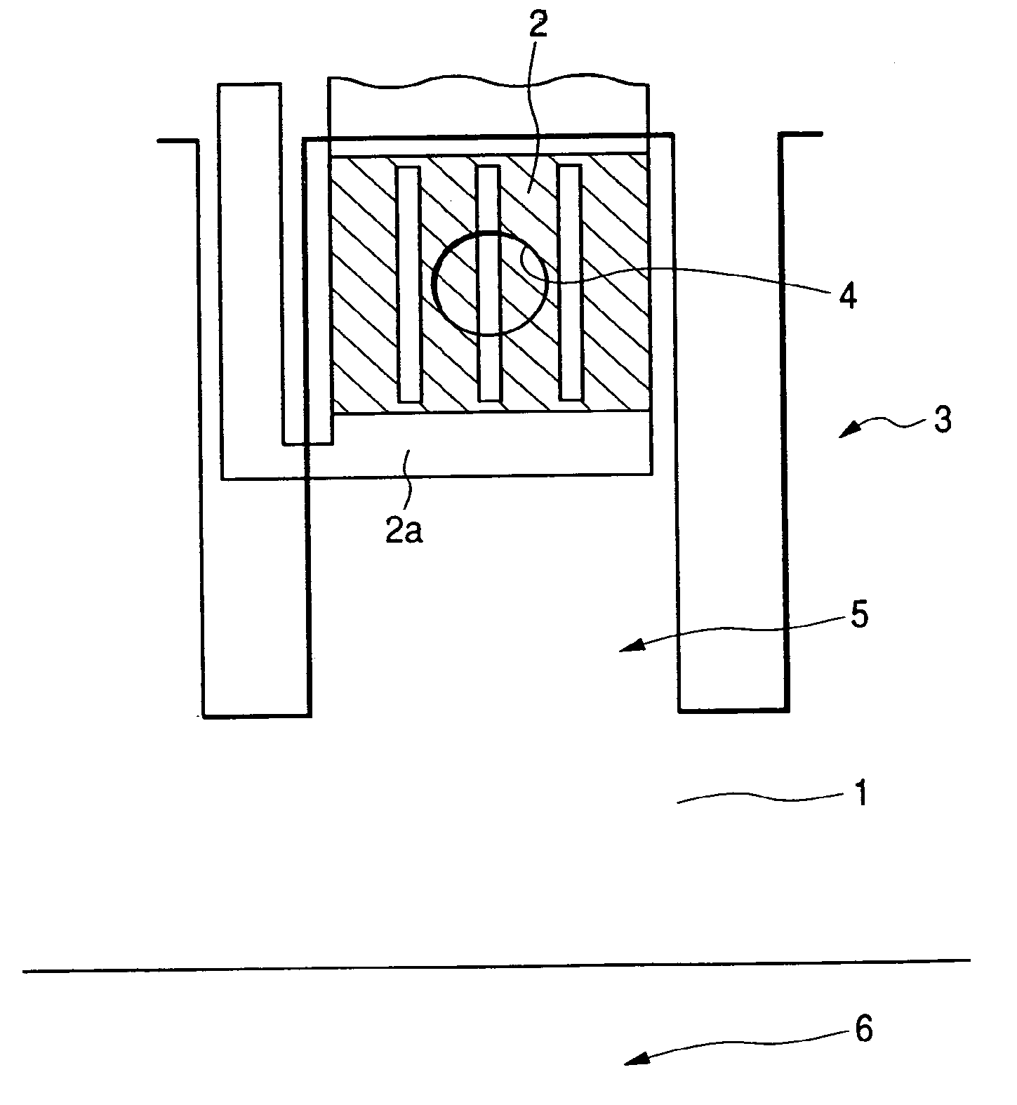
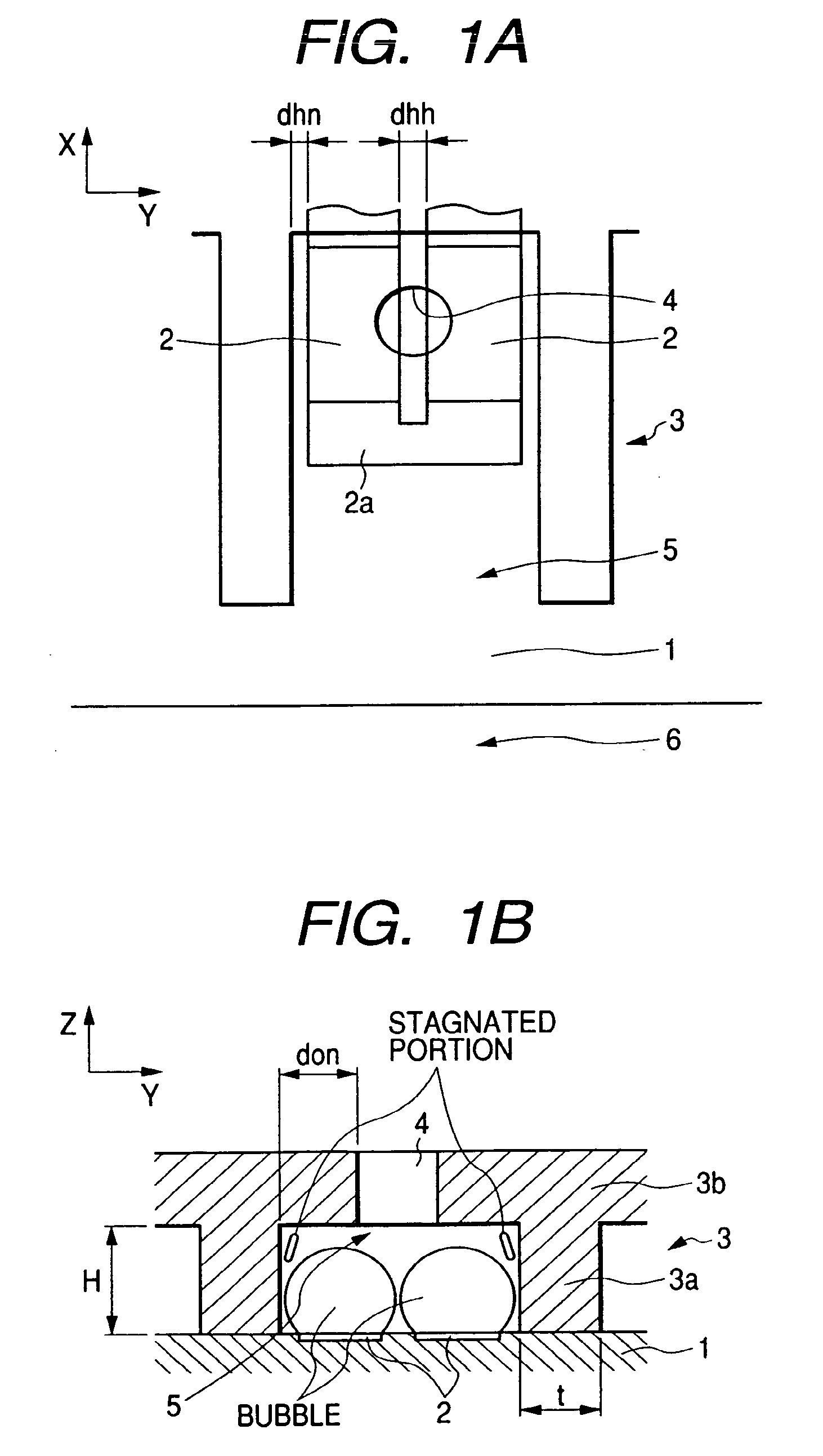
[0037]FIGS. 1A and 1B are a perspective view and a cross-sectional view for explaining the positional relationship of an ink flow path, heat generating elements, and a discharge port for an ink jet head according to a first embodiment of the present invention.

[0038]The ink jet head of the embodiment comprises: a substrate 1, on the surface of which multiple heat generating elements 2 are provided; and a flow path formation member 3, formed on the substrate 1. The flow path formation member 3 is composed of a photosensitive epoxy resin, for example, and includes partition walls 3a, which are used to define heat generating element sets of two elements each, and a ceiling 3b opposite the substrate 1. The partition walls 3a also define multiple ink flow paths 5, along each of which ink is supplied to two heat generating elements 2. Further, for each of the ink flow paths 5, a discharge port 4 is formed in the ceiling 3b along a line that extends, in the normal direction, from the center...

second embodiment

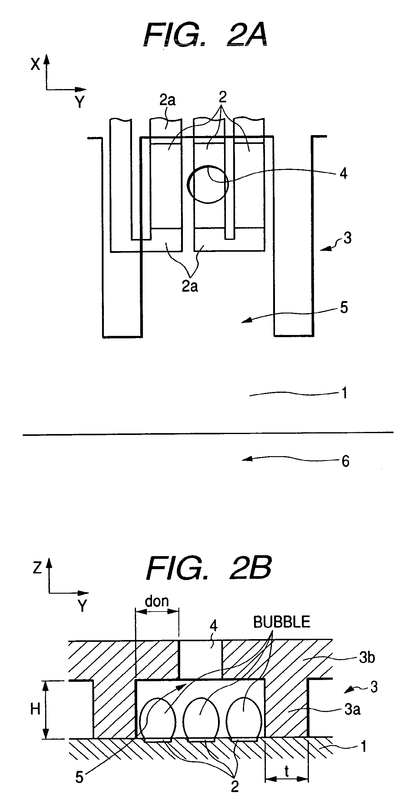
[0058]FIGS. 2A and 2B are a plan view and a cross-sectional view of the positional relationship of ink flow paths, heat generating elements and discharge ports for an ink jet head according to a second embodiment of the present invention.

[0059]As is shown in FIGS. 2A and 2B, for the ink jet head of this embodiment, three heat generating elements 2 are arranged in parallel in each flow path 5, between opposed partition walls 3a that define the ink flow path 5, and are electrically connected, in series, by wiring lines 2a. For each ink flow path 5, a discharge port 4 is formed in a ceiling 3b along a line extending from the center of a pressure generation region, formed by three heat generating elements 2, in the normal direction of the surface of the substrate 1.

[0060]Table 2 shows the sizes of the individual sections of a sample 2a, for the ink jet head of this embodiment, and the response frequency and discharge stability evaluation results obtained therewith.

[0061]

TABLE 2Head Size...

third embodiment

[0064]FIGS. 3A and 3B are a plan view and a cross-sectional view of the positional relationships of ink flow paths, heat generating elements and a discharge port for an ink jet head according to a third embodiment of the present invention.

[0065]Especially, as is shown in FIG. 3A, for the ink jet head of this embodiment, a set of four heat generating elements 2 are provided in one ink flow path 5. Of these heat generating elements 2, two are arranged in the X direction and the other two are arranged in the Y direction, where the X direction denotes the direction in which ink flows along the ink flow path 5, and the Y direction denotes the direction perpendicular to the X direction and parallel to the surface of a substrate 1, i.e., the direction across those partition walls 3a that define an ink flow path 5. Further, these heat generating elements 2 are electrically connected, in series, by wiring lines, and a discharge port 4 is formed along a line extending from the center of a pre...


PUM


Abstract

An ink jet head according to the present invention includes multiple discharge ports for discharging ink, multiple ink flow paths for communicating with the discharge ports, and heat generating elements for generating bubbles in ink filling the ink flow paths. For each ink flow path, two heat generating elements are arranged therein, and the discharge port is arranged along a line that is extended, from the center of a pressure generation region formed by the two heat generating elements, in the normal direction relative to the surface of the substrate. The arrangement pitch of the heat generating elements is equal to or greater than 600 dpi, and the interval dhn between a partition wall defining an ink flow path and the heat generating element adjacent to the partition wall is equal to or smaller than 4 μm.

Description

BACKGROUND OF THE INVENTION[0001]1. Field of the Invention[0002]The present invention relates to an ink jet head that performs recording by discharging ink onto a recording medium.[0003]2. Related Background Art[0004]Because producing high quality characters and images is easy with ink jet recording apparatuses, such output devices are widely employed today, especially for computers. Above all, bubble jet systems, wherein ink is forcefully discharged from nozzles by utilizing extremely powerful pressure changes produced by the instantaneous boiling of ink in the nozzles, have become the leading, preferred ink jet recording apparatuses.[0005]Further, as the popularity of ink jet recording apparatuses has grown, so too has the number of requests for improved performance, especially as it pertains to image quality and recording speeds. And since to improve image quality, the diameters of dots formed on a recording medium (specifically, on a recording sheet) are especially important, gr...

Claims


Application Information

Patent Timeline
IPC IPC(8): B41J2/14B41J2/05
CPCB41J2/1404B41J2/14056B41J2/1412B41J2002/14387B41J2002/14177B41J2002/14169
Inventor KANEKO, MINEOTSUCHII, KENTSUKUDA, KEIICHIROOIKAWA, MASAKIYABE, KENJI
Owner CANON KK
Why Eureka
Try Eureka