Three-dimensional display using variable focusing lens

a three-dimensional display and variable focusing technology, applied in the field of three-dimensional display, can solve the problems of unsuitable display for displaying realistic 3d images, the method does not generate a three-dimensional image in the space, and the use of holography for three-dimensional image display is limited, so as to achieve the effect of no significant increase in data amount, easy conversion, and low cost for providing three-dimensional image data

Active Publication Date: 2006-07-18
STEREO DISPLAY
View PDF10 Cites 93 Cited by
  • Summary
  • Abstract
  • Description
  • Claims
  • Application Information

AI Technical Summary

Benefits of technology

[0008]An objective of the invention is to provide a three-dimensional display device that has a simple construction and realistic image representation.
[0022]The advantages of the present invention are: (1) since the three-dimensional display device actually generates three-dimensional images in the space, the device does not suffer from the disadvantage of prior art device using parallax including imaging difficulties due to considerations for arbitrary distribution of the viewer's position, and binocular disparity due to deviations in the distance between the two eyes, vergence, accommodation, watching by more than one viewers, and the relative position change of the three-dimensional image due to viewer's movement; (2) the cost for providing three-dimensional image data is inexpensive since the data needs only depth information in addition to two-dimensional image information, and thus there is no significant increase in data amount; and (3) the device can be easily converted to a two-dimensional display and vice versa.

Problems solved by technology

This method does not actually generate a three-dimensional image in the space.
Therefore, this method has disadvantages that various factors including arbitrary distribution of the viewer's position, binocular disparity due to deviations in the distance between the two eyes, vergence, fatigue accumulation in the eye, accommodation, watching by more than one viewers, the relative position change of the three-dimensional image due to viewer's movement, etc., are involved, and such factors must be considered in order to provide proper three-dimensional display.
Holography has been used for three-dimensional image display very limitedly due to its technical complexity and high manufacturing cost.
Austin's display has a disadvantage that since the focus changing speed of the fluid-filled lens is slow, the display is unsuitable for displaying realistic 3D images.

Method used


Image

  • Three-dimensional display using variable focusing lens
  • Three-dimensional display using variable focusing lens
  • Three-dimensional display using variable focusing lens

Examples


first embodiment

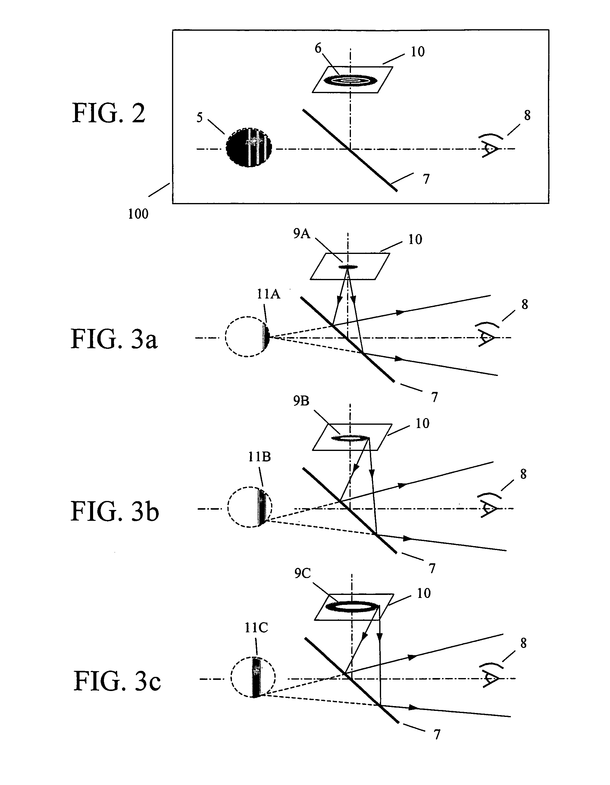
[0042]FIG. 2 schematically shows a 3D (three-dimensional) display device 100 according to the present invention. The 3D display device 100 includes a 2D (two-dimensional) display 10 displaying a first image 6, and a variable focusing lens 7 receiving light from the 2D display 10 and forming a second image 5. The variable focusing lens 7 changes its focal length so that the second image 5 looks three-dimensional for a viewer 8 of the three-dimensional display device 100.

[0043]A 3D image is generated in the space by imaging depthwise 2D images on corresponding depths in the space with the variable focusing lens. The 2D display displays only pixels that should be imaged at the same depth at a given moment or a given frame, and the variable focusing lens adjusts its focal length in order to image the depthwise image to the required location in the space.

[0044]FIGS. 3a–3c show that the first image 6 includes a predetermined depth number of first depthwise images 9A, 9B, 9C that are displ...

second embodiment

[0064]FIGS. 8a and 8b shows the present invention. FIG. 8a shows how a 3D display device, which has variable focusing lenses 23 corresponding to pixels 26 of a 2D display 22, operates to display a three-dimensional image 24. The partial image displayed by each pixel 26 is imaged at its image depth by the variable focusing lens 23 corresponding to the pixel 26. Since the partial image displayed by each pixel is individually handled by the corresponding variable focusing lens, dividing an image into depthwise images and displaying the depthwise images are not required, and thus this embodiment does not need a high speed 2D display and a high speed variable focusing lens. A 2D display having a usual speed can be used. The size of the variable focusing lens 23 is similar to that of the pixel 26.

[0065]FIG. 8b shows schematically a 3D display device 200. The 3D display device 200 includes a 2D display having a plurality of pixels 26, and a plurality of variable focusing lenses 25. Each of...


PUM

PropertyMeasurementUnit
image depthaaaaaaaaaa
angleaaaaaaaaaa
focal lengthaaaaaaaaaa

Abstract

A three-dimensional display device includes a two-dimensional display displaying a first image, and a variable focusing lens receiving light from the two-dimensional display and forming a second image. The variable focusing lens reflects light from the two-dimensional display. The first image includes a predetermined number of first depthwise images that are displayed within a unit time, and the second image includes corresponding second depthwise images. Each depthwise image represents the portion of the first image having the same image depth, and the two-dimensional display displays one depthwise image at a time. The focal length of the variable focusing lens changes according to the depth of the depthwise image being displayed. A micromirror array lens is used as the variable focusing lens. The micromirror array lens has enough speed and focusing depth range for realistic three-dimensional display.

Description

BACKGROUND OF THE INVENTION[0001]The present invention relates to a method and a device for three-dimensional display. More particularly, this invention relates to a method and a device for three-dimensional display using a variable focusing lens combined with a two-dimensional display.[0002]The most popular method for three-dimensional display by prior art is one using the binocular parallax phenomenon. This method utilizes the principle that the human brain perceives a three-dimensional image when each eye sees one of two images that are measured at different angles. This method does not actually generate a three-dimensional image in the space. Rather, parallax by the observer's eyes is utilized. Therefore, this method has disadvantages that various factors including arbitrary distribution of the viewer's position, binocular disparity due to deviations in the distance between the two eyes, vergence, fatigue accumulation in the eye, accommodation, watching by more than one viewers,...

Claims


Application Information

Patent Timeline
Patent Type & Authority Patents(United States)
IPC IPC(8): G03B21/00G02B26/00G02B27/14G02B5/08G03B21/20A61B3/14G02B5/32G02B27/10G02B27/22G02F1/1335H04N13/395
CPCG02B27/2278G03B21/00H04N13/0497H04N13/0495H04N13/042G03B35/00G03B21/008H04N13/395H04N13/322H04N13/398G02B30/52
Inventor SEO, CHEONG SOOGIM, DONG WOOCHO, GYOUNG ILBOYD, JAMES GREENUPBAEK, SANG HYUNE
Owner STEREO DISPLAY
Why Eureka
Try Eureka