Preform conveying device

a conveying device and a technology for transferring materials, applied in the directions of transportation and packaging, food shaping, other domestic objects, etc., can solve the problems of high frequency of soiling of the preform surface, damage to the preform, etc., and achieve the effect of smoother slipping between the grips and the preforms

Inactive Publication Date: 2006-07-18
YOSHINO KOGYOSHO CO LTD +1
View PDF8 Cites 6 Cited by
  • Summary
  • Abstract
  • Description
  • Claims
  • Application Information

AI Technical Summary

Benefits of technology

[0014]Also, since only the preforms are moved to the blow molding process or other subsequent process side and since movement to the subsequent process side, return to the conveying device, and realignment are thus made unnecessary for the supporting parts, the conveying device can be made simple in structure and handling.
[0017]With the arrangement of the second aspect, since the slide table can be raised or lowered to set the height position of the supporting parts to an appropriate position, the transfer of the preforms from the unloading device can be performed more smoothly and the degree of freedom of the configuration of the injection molding machine, unloading device, and conveying device can be increased.
[0018]Also, by combining the operation of the unloading device and the rising / lowering operation of the slide table, the time required for transferring the preforms can be shortened.
[0020]Though with regard to the arrangement of a supporting part, for example a method of providing an indented part into which the mouth part of the preform is fitted, a method of providing a protruding part that is fitted into the mouth part, etc., may be employed according to purpose, with the above-described arrangement of the third aspect, even if there is a slight positional deviation and there is a slight tilt in the orientation of a preform when the preform is transferred from the unloading device to a supporting part, the head part can accommodate for this deviation and tilt by tilting to enable smooth transfer to be achieved, the tolerance of the precision of the positioning of devices to be widened, the device arrangement to be simplified, the time required for positional adjustments to be shortened, and thus the production speed to be improved.
[0021]Also, when a preform is transferred from a slide plate to the grip conveyer, the downstream part of the grip conveyer is raised and set in an inclined manner to pull up and remove the preform from a supporting part, and this removal can be carried out smoothly by making the head part swingable in orientation. Production problems can thus be prevented and the widening of the tolerance of the precision of the positioning of devices, simplification of the device arrangement, and improvement of the production speed are enabled for this reason as well.
[0025]With the above-described arrangement of the fifth aspect, when the movement of the preforms is disabled for some reason and a load of a fixed range or more is generated, since the parallelogram shapes of the grips collapse further in the direction opposite the direction of progress of the chain and flatten, the slipping between the grips and preforms is made smoother.

Problems solved by technology

However, if the production speed is to be increased further, the preforms must be handled in a state of higher temperature, and with the prior-art method illustrated in FIG. 6, the preforms can get damaged due to collision or friction of preforms with themselves or with device parts.
Also, due to the high probability for preform surfaces coming in contact with parts that make up the device, soiling of preform surfaces occurs at a high frequency.

Method used


Image

  • Preform conveying device
  • Preform conveying device
  • Preform conveying device

Examples


Embodiment Construction

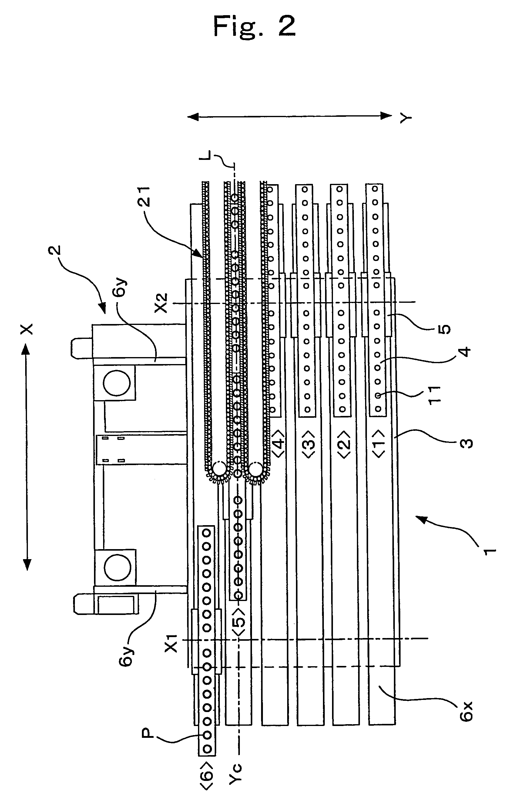
[0032]An embodiment of this invention's conveying device shall now be described with reference to FIGS. 1 through 5.

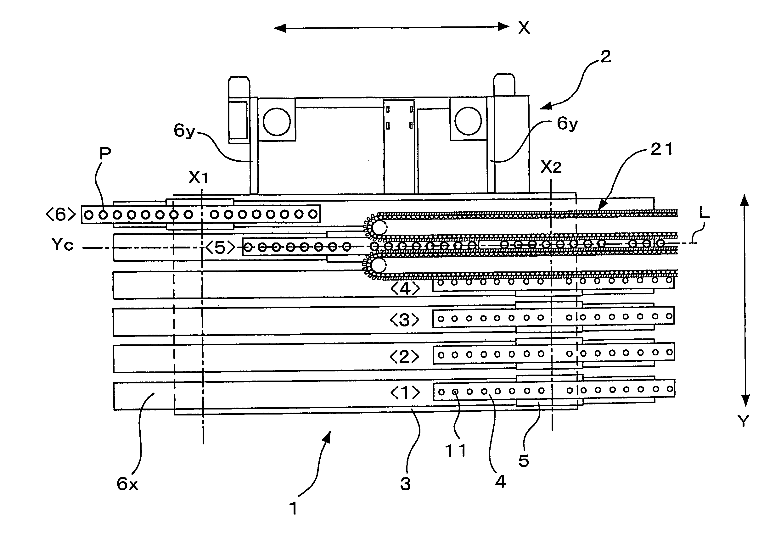
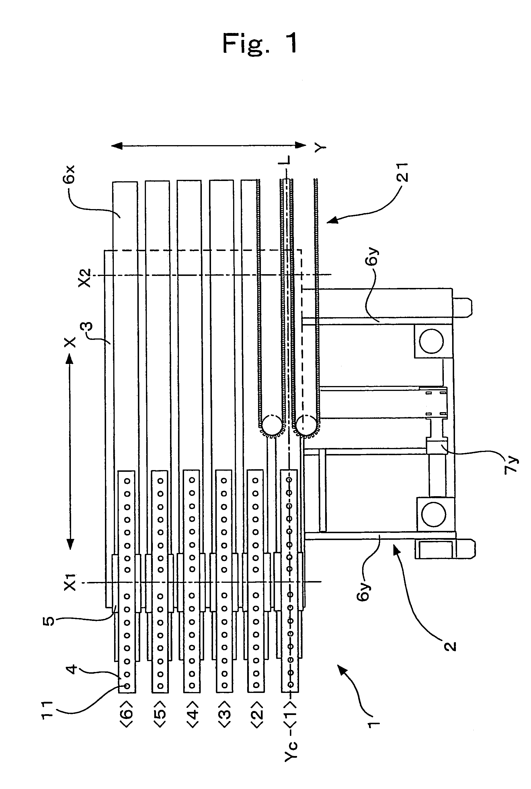
[0033]FIG. 1 is a plan view showing an embodiment of this invention's conveying device and shows a state prior to the receiving of preforms P from an unloading device 31 by conveying device.

[0034]As shown in FIG. 1, conveying device comprises a frame 2, a slide table 3, which is slidably mounted on frame 2, six slide plates 4, disposed in parallel on slide table 3, a grip conveyor 21, etc., and a preform alignment part 1 is formed by the six slide plates 4.

[0035]Frame 2 is equipped with two Y-axis rails 6y, which run parallel along a Y-direction, and slide table 3 is set on Y-axis rails 6y in a manner such that it is movable with its upper face being horizontal. Frame 2 is provided with a Y-axis servo motor 7y and slide table 3 is driven along Y-axis rails 6y by Y-axis servo motor 7y. Furthermore, the entirety of slide table 3, including Y-axis servo motor 7y, is suppo...


PUM

PropertyMeasurementUnit
speedaaaaaaaaaa
conveying speedaaaaaaaaaa
shapeaaaaaaaaaa

Abstract

An object of this invention is to provide a preform conveying device of high production efficiency under the technical theme of aligning the plurality of preforms in single rows at high speed, while eliminating contact of individual preforms with other preforms and minimizing the chances of contact with device parts.In a state in which a plurality of preforms are aligned vertically and laterally, preforms are received in a manner partitioned in vertical row units, and by putting a conveying line, formed along the direction of a vertical row of preforms, in an inclined orientation in which the downstream side is raised, positioning the upstream end of the conveying line above a preform receiving part, and moving the vertical row unit of preforms that is positioned along the conveying line in the vertical row direction at substantially the same speed as the conveying speed of the conveying line, the respective preforms of the vertical row unit are transferred in a state in which each is sandwiched by the conveying line and this is carried out successively for each vertical row unit to supply the plurality of preforms to a blow molding machine or other subsequent process side upon aligning them in single rows.

Description

FIELD OF THE ART[0001]This invention relates to a preform conveying device to be used in manufacturing a molded container, such as a polyethylene terephthalate resin bottle, etc., and more specifically relates to a device, which receives, via an unloading device, preforms, molded by an injection molding machine having a plurality of preform molding cavities aligned vertically and laterally, aligns these preforms in single rows, and supplies the preforms to a blow molding machine or subsequent process side.BACKGROUND ART[0002]Due to their performance, the applications of bottles and other containers formed of a biaxial drawing, blow-molded thermoplastic resin, such as polyethylene terephthalate (PET) resin, etc., are spreading greatly in a wide variety of fields, such as drink bottles, etc. Normally, such molded containers are manufactured by heating and melting a plastic material by an injection molding machine to injection mold test-tube-shaped preforms, conveying these preforms to...

Claims


Application Information

Patent Timeline
Patent Type & Authority Patents(United States)
IPC IPC(8): B29C49/42B29C49/06B29L22/00B65G15/14
CPCB29C49/064B29C49/4205B29C49/06Y10S425/038B29L2031/7158B29C2049/4231B29K2067/00B29C49/42057B29C49/42067B29C49/42085B29C49/42101B29C49/42105B29C2049/023B29C2949/0715B29C49/6427
Inventor HIRASAWATSU, TADAOAMARI, SHIGEAKIKATO, GOICHI
Owner YOSHINO KOGYOSHO CO LTD
Why Eureka
Try Eureka