
Radiographic apparatus and radiographic system

a radiographic system and apparatus technology, applied in the field of radiographic apparatus and radiographic system, can solve the problems of affecting the quality of sensed images, the position of sensors is a problem, and the cost of the entire apparatus increases

Inactive Publication Date: 2006-07-18
CANON KK
View PDF10 Cites 18 Cited by
  • Summary
  • Abstract
  • Description
  • Claims
  • Application Information

AI Technical Summary

Benefits of technology

The present invention provides a radiographic apparatus that can automatically adjust the incident radiation amount while suppressing attenuation of radiation before detection. The apparatus includes a substrate, conversion devices, and wiring lines connected to the conversion devices. The second semiconductor conversion devices are collectively arranged in a region where the first semiconductor conversion devices connected to a specific printed wiring board are collectively arranged. This arrangement ensures that the second semiconductor conversion devices do not interfere with the operation of the first semiconductor conversion devices. The technical effect of the invention is to improve the quality of sensed images while reducing the cost of the entire apparatus.

Problems solved by technology

However, when a separate AEC control sensor is used to adjust (AEC-control) the incident radiation amount, the position of the sensor poses a problem.
Hence, the cost of the entire apparatus increases.
In addition, there is no sensor that causes no attenuation at all, the quality of sensed images inevitably degrades.
Since the wiring capacitance increases, noise increases.
In addition, since the opening ratio of the image sensing radiation detection pixels greatly decreases, the image quality becomes poor.

Method used


Image

  • Radiographic apparatus and radiographic system
  • Radiographic apparatus and radiographic system
  • Radiographic apparatus and radiographic system

Examples


first embodiment

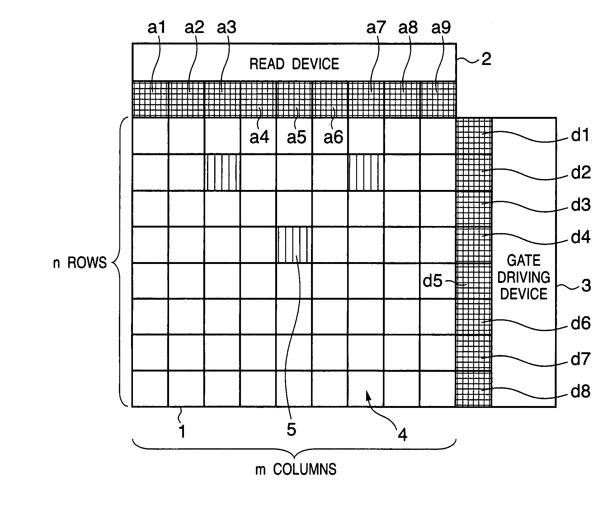
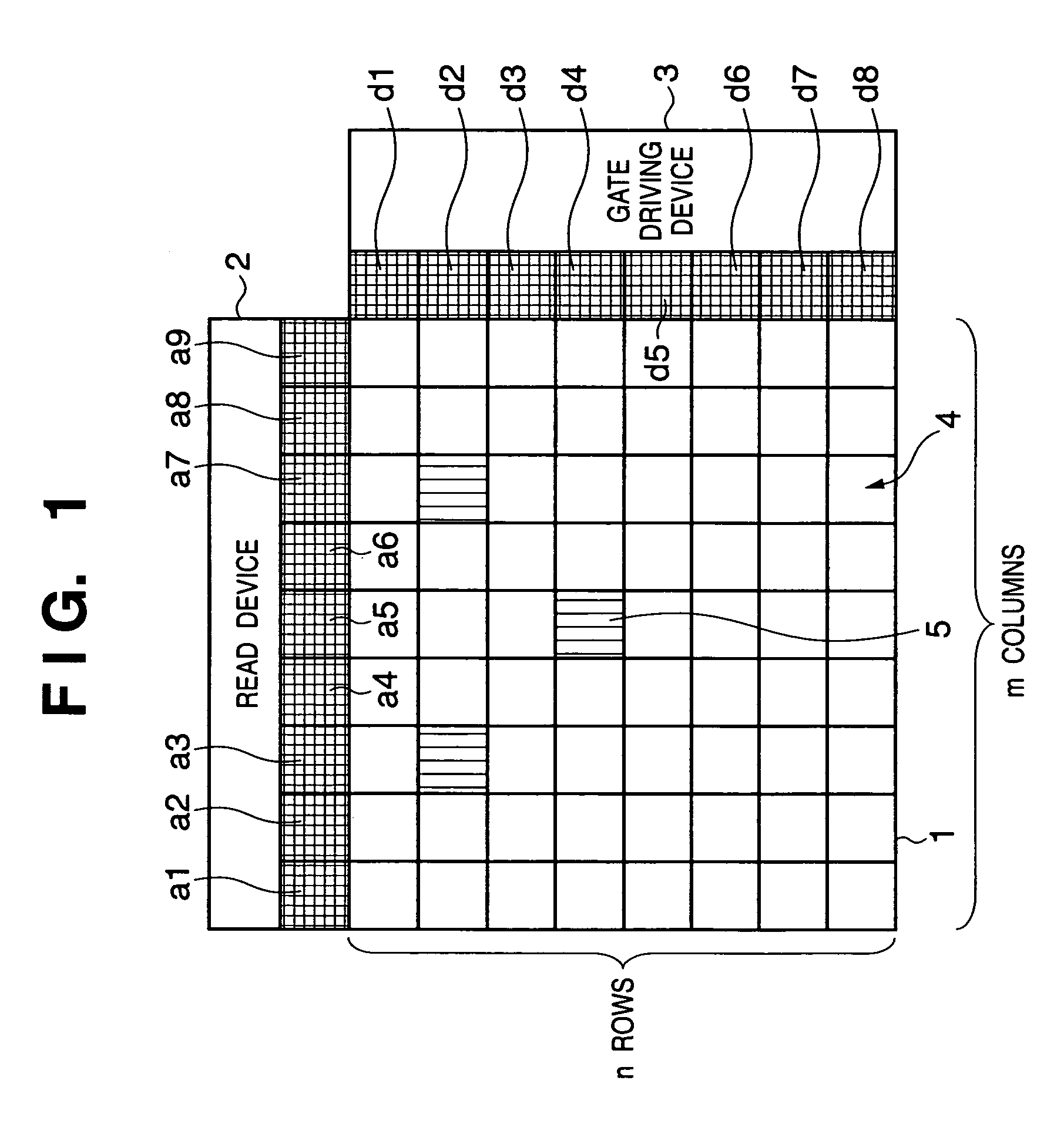
[0025]The first embodiment of the present invention will be described. FIG. 1 is a schematic view showing the layout of a radiation detection apparatus according to the first embodiment of the present invention.

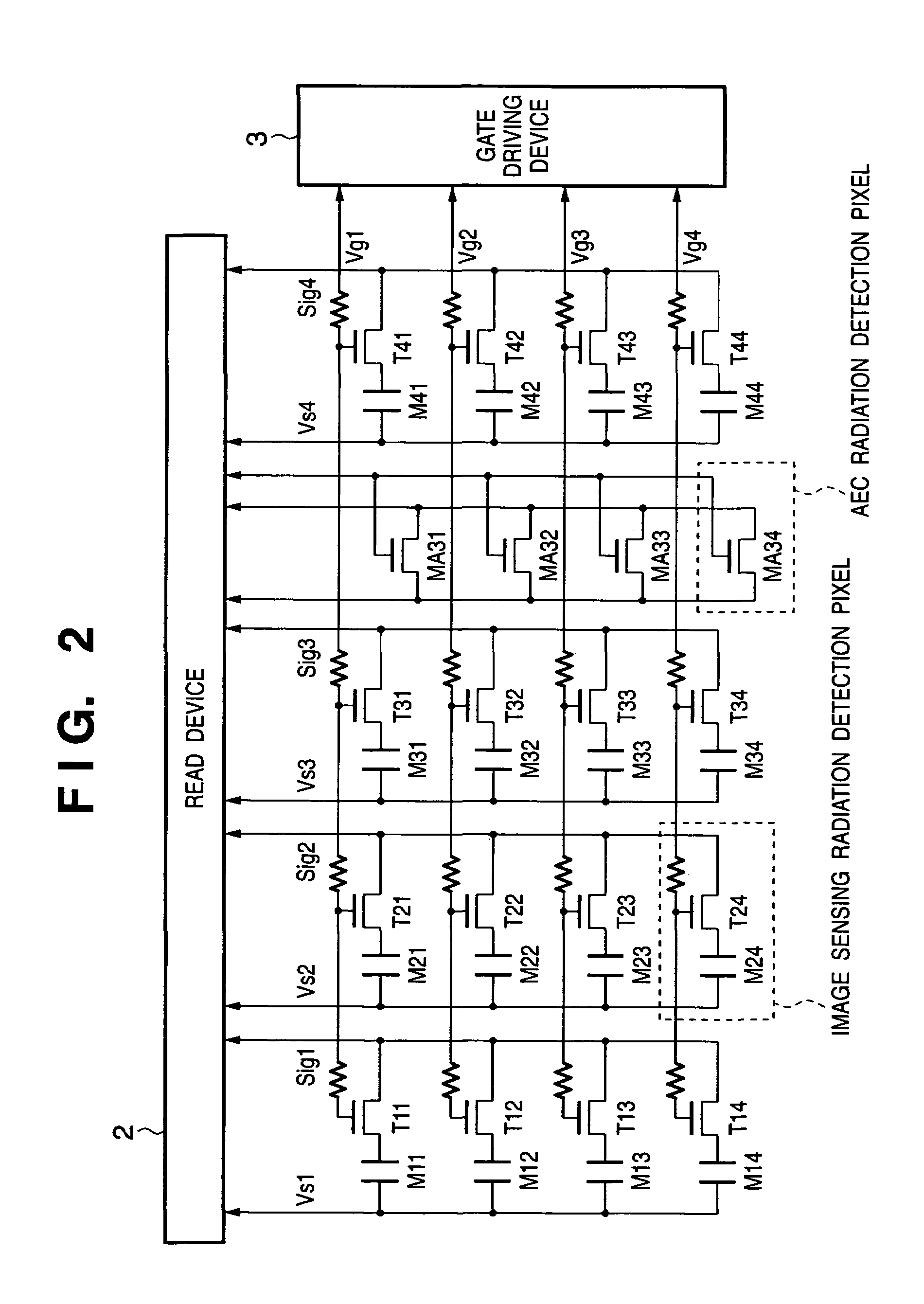
[0026]In this embodiment, m (columns)×n (rows) image sensing radiation detection pixels are arranged in a matrix on an insulating substrate 1. An image sensing radiation detection pixel has a conversion portion which is constituted by an MIS photoelectric conversion device (first semiconductor conversion device) and a read thin-film transistor (TFT) (switching device) to convert radiation into an electrical signal. The image sensing radiation detection pixels of m columns are divided into, e.g., nine groups. The image sensing radiation detection pixels of each group are connected to a corresponding one of read TCPs a1 to a9. The image sensing radiation detection pixels of n rows are divided into, e.g., eight groups. The image sensing radiation detection pixels of each group a...

second embodiment

[0056]The second embodiment of the present invention will be described next. FIG. 5 is a schematic view showing the layout of a radiation detection apparatus according to the second embodiment of the present invention.

[0057]Even in this embodiment, as in the first embodiment, m (columns)×n (rows) image sensing radiation detection pixels are arranged in a matrix on an insulating substrate 1. The image sensing radiation detection pixels of m columns are divided into, e.g., nine groups. The image sensing radiation detection pixels of n rows are divided into, e.g., eight groups. The image sensing radiation detection pixels of each group are connected to a corresponding one of driving TCPs d1 to d8. Of the image sensing radiation detection pixels of m columns divided into nine groups, each of pixels connected to one of the driving TCPs d1 to d4 is connected a corresponding one of read TCPs a1 to a9. Each of pixels connected to one of the driving TCPs d5 to d8 is connected a corresponding...

application example

(Application Example)

[0068]A radiographic system which uses the radiographic apparatus according to the preferred embodiment of the present invention will be described below. FIG. 10 is a schematic view showing an application example of the radiographic apparatus according to the preferred embodiment of the present invention to a radiographic system.

[0069]X-rays 6060 generated by an X-ray tube 6050 are transmitted through a breast part 6062 of a patient or examination subject 6061 and become incident on a radiation detection apparatus (radiographic apparatus) 6040 as shown in FIG. 1. The incident X-rays contain the internal information of the patient 6061. In accordance with the incidence of the X-rays, the scintillator (phosphor) emits light. The light is photoelectrically converted by the photoelectric conversion devices of the sensor panel so that electrical information is obtained. The radiation detection apparatus (radiographic apparatus) 6040 outputs this information to an ima...


PUM


Abstract

Image sensing radiation detection pixels of m (columns)×n (rows) are divided into, e.g., 72 pixel regions. Image sensing radiation detection pixels belonging to one pixel region are connected to the same read TCP and driving TCP. For example, three regions (AEC radiation detection regions) of the 72 pixel regions have a plurality of AEC radiation detection pixels. An AEC radiation detection pixel has a TFT sensor. Spare wiring lines for the AEC radiation detection pixels are arranged at two side portions of each read TCP. Each spare wiring line is connected to a predetermined circuit in a read device to connect the AEC radiation detection pixels to the predetermined circuit so that the AEC circuit is operated.

Description

FIELD OF THE INVENTION[0001]The present invention relates to a radiographic apparatus and radiographic system which can suitably be used for a medical image diagnostic apparatus, nondestructive inspection apparatus, analyzing apparatus using radiation, and the like. In this specification, radiation includes visible light and electromagnetic waves such as and X-rays in addition to α-rays, β-rays, and γ-rays.BACKGROUND OF THE INVENTION[0002]As a method of irradiating an object with radiation and detecting the intensity distribution of the radiation transmitted through the object to obtain the radiographic image of the object, a technique has recently been developed, in which a digital image is acquired by using a photoelectric conversion apparatus in which pixels comprised of small photoelectric conversion devices and switching devices are arrayed in a matrix. Such radiographic apparatuses can immediately display acquired image data.[0003]In a conventional radiographic apparatus, when...

Claims


Application Information

Patent Timeline
Patent Type & Authority Patents(United States)
IPC IPC(8): H04N5/32G01T1/29G21K4/00
CPCG01T1/2928G21K4/00H04N5/32H04N25/30H04N25/706
Inventor ISHII, TAKAMASAMORISHITA, MASAKAZUYAMAZAKI, TATSUYATSUJII, OSAMUHIRAI, AKIRATAMURA, TOSHIKAZUNONAKA, HIDEKI
Owner CANON KK
Learn More