Vehicle AC generator apparatus having improved generator control apparatus

a generator and control apparatus technology, applied in the direction of electric generator control, electric generator control, dynamo-electric converter control, etc., can solve the problems of large overall scale of the generator control apparatus, engine cranking operation, and inability to provide a single type of generator control apparatus, so as to achieve easy and accurate adjustment of the level of current flow in the excitation winding

Inactive Publication Date: 2006-07-18
DENSO CORP
View PDF15 Cites 26 Cited by
  • Summary
  • Abstract
  • Description
  • Claims
  • Application Information

AI Technical Summary

Benefits of technology

[0011]It is an objective of the present invention to overcome the above problems, by providing an AC generator apparatus having a generator control apparatus whereby it is ensured that a charging warning lamp is controlled to provide a reliable indication of the electrical generation status of the AC generator apparatus, irrespective of the effects of leakage current of a rectifier apparatus.
[0012]It is a further objective to provide an AC generator apparatus having a generator control apparatus that is applicable to various different types of AC generator apparatus, to thereby minimize the number of different types of such generator control apparatus that must be manufactured, and whereby the generator control apparatus is configured such that the AC generator apparatus can be of compact size.
[0013]Basically, the present invention achieves the above objectives by providing a vehicle AC generator apparatus having a rectifier apparatus, and a generator control apparatus which (after the vehicle ignition has been switched on prior to starting the vehicle engine) detects the point at which power generating begins, i.e., when the engine begins to fire, by detecting when the voltage across a rectifier element (in general, a diode) of the rectifier apparatus first becomes higher than the positive-polarity output terminal of the rectifier apparatus, or by detecting when the voltage across a rectifier element first becomes lower (more negative) than the negative-polarity output terminal of the rectifier apparatus. Such a condition first occurs when forward conduction by the rectifier elements begins, after engine starting, and so provides a highly accurate indication of the timing of commencement of power generation operation. Based on that detection, controlled parameters such as the level of current through a charging warning lamp, and the level of excitation current of the generator, can be reliably changed over immediately when engine starting is completed and electric power generation begins.

Problems solved by technology

As a result, the charging warning lamp may remain in the off state after the vehicle ignition has been switched on but no electrical generation is being performed.
Hence, with such a prior art method, it is not possible to provide a single type of generator control apparatus that will be suitable for use with AC generator apparatuses that may be of type A or type B. It has thus been necessary to use a plurality of different types of generator control apparatus, incorporating respectively different types of leakage compensation circuits, in accordance with the specifications of various types of AC generator apparatus.
However in order to detect a low frequency component it is necessary to use a circuit having a large time constant, so that the leakage compensation circuit will have a complex configuration, i.e., formed of capacitors, resistors, counters, etc.
Thus, the overall scale of the generator control apparatus will become large.
Moreover, when such a method is used, whereby the lowest frequency component is detected, the charging warning lamp will become turned off when engine cranking is occurring, during engine starting.
On observing this, the vehicle driver may erroneously believe that engine starting has been achieved, and so halt the engine cranking operation before engine starting has actually occurred.

Method used


Image

  • Vehicle AC generator apparatus having improved generator control apparatus
  • Vehicle AC generator apparatus having improved generator control apparatus
  • Vehicle AC generator apparatus having improved generator control apparatus

Examples


Embodiment Construction

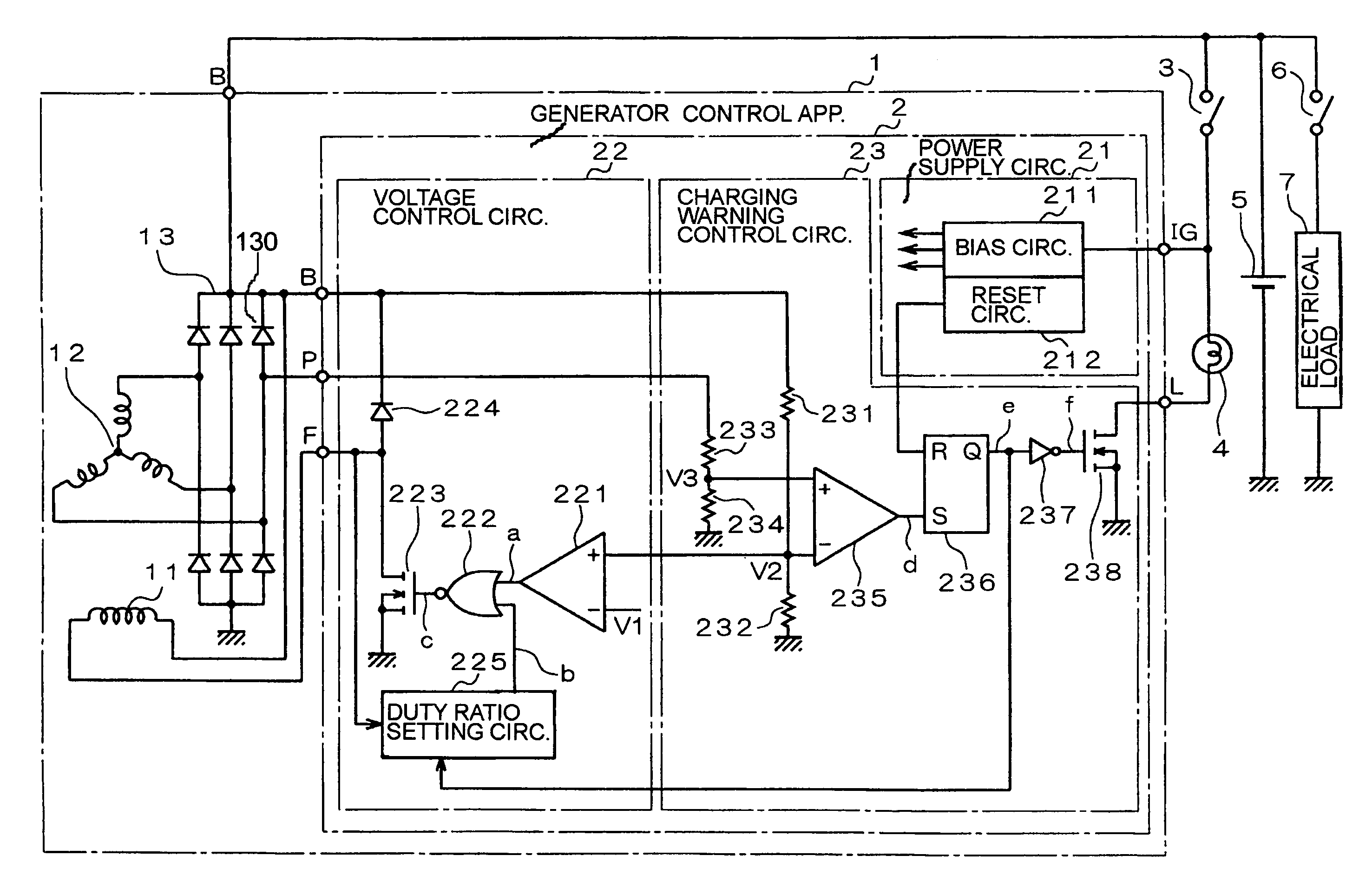
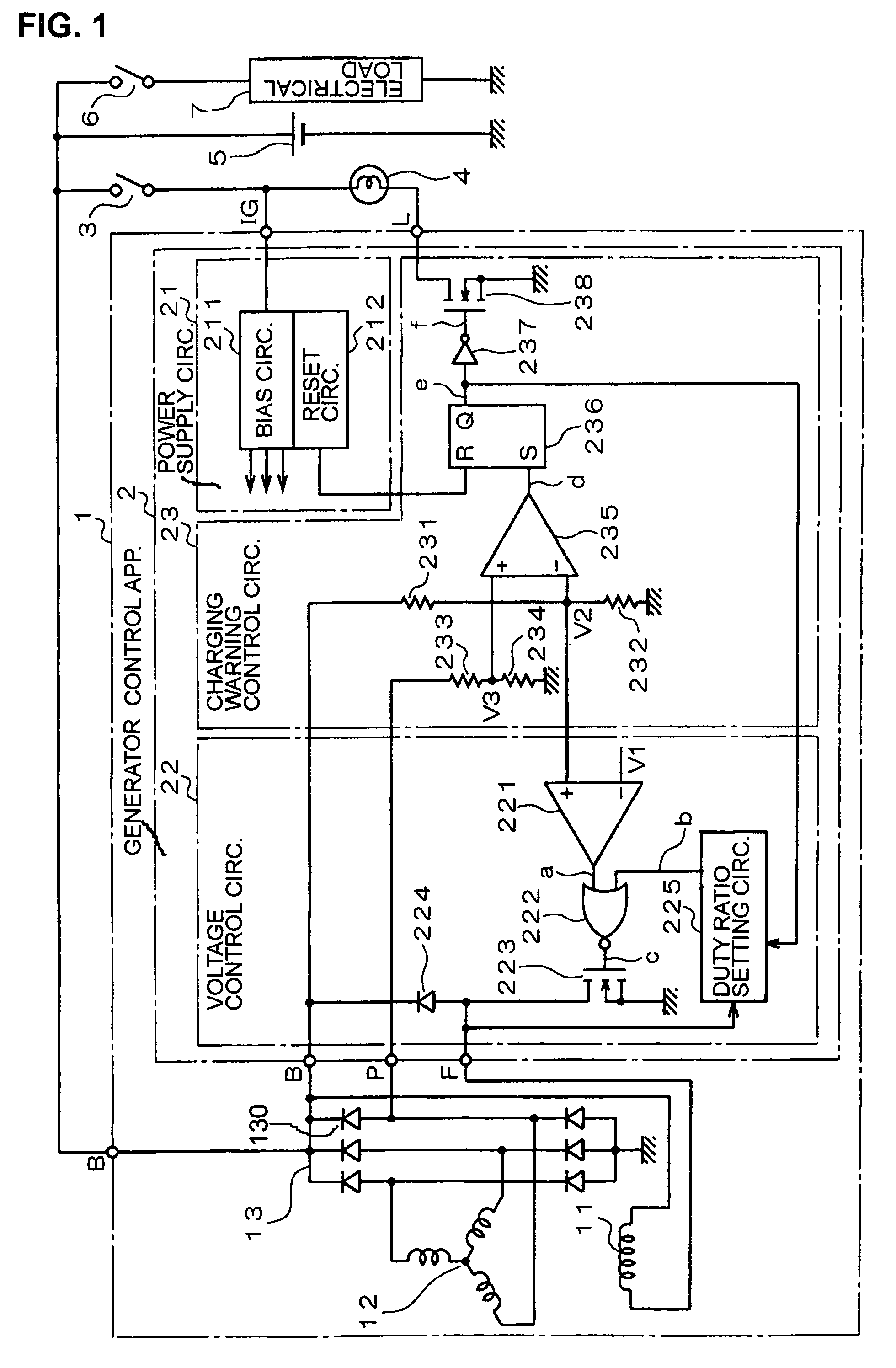
[0024]FIG. 1 is a circuit diagram showing the configuration of an embodiment of an AC generator apparatus for a vehicle. In particular, the diagram shows the connection conditions between the AC generator apparatus, designated by numeral 1, and a battery 5, a switch 3, etc. The switch 3 may function also as the ignition switch of the vehicle, i.e., it becomes closed when the vehicle ignition is turned on, prior to performing engine starting. As shown in FIG. 1, the AC generator apparatus 1 is basically made up of an excitation winding 11, an armature winding 12, which in this embodiment is a 3-phase winding, a rectifier apparatus 13 and a generator control apparatus 2.

[0025]The AC generator apparatus 1 includes a rotor (not shown in the drawings) having a plurality of field poles (not shown in the drawings) and a stator (not shown in the drawings) having the armature winding 12 wound on a magnetic core. The excitation winding 11 serves to magnetize the field poles of the rotor. The ...


PUM


Abstract

A vehicle AC generator apparatus includes one or more rectifier elements for rectifying a generated AC voltage, and a generator control apparatus which monitors the voltage difference between opposing terminals of a rectifier element, to thereby detect the commencement of electrical generation upon engine starting as the time point at which the polarity of the voltage difference first corresponds to the forward conduction direction of the rectifier element. Controlled parameters such as the current supplied to a charging warning lamp and the excitation current of a generator winding are changed appropriately when generation commencement is detected.

Description

CROSS-REFERENCE TO RELATED APPLICATIONS[0001]This application is based on and incorporates herein by reference Japanese Patent Application No. 2003-308233 filed on Sep. 1, 2003 and 2004-192379 filed on Jun. 30, 2004.BACKGROUND OF THE INVENTION[0002]1. Field of Technology[0003]The present invention relates to an AC generator apparatus for use in a motor vehicle, where the term “AC generator apparatus” is used in the following description to signify a generator apparatus driven by a vehicle engine, which generates an AC voltage and rectifies that AC voltage to derive an output DC voltage.[0004]2. Description of Prior Art[0005]A vehicle AC generator apparatus supplies electric power, as a rectified DC voltage, to the battery of the vehicle and to various electrical equipment, with the output voltage of the generator regulated to a predetermined value by a generator control apparatus. In general, the generator control apparatus (sometimes referred to as voltage regulator) adjusts an AC ...

Claims


Application Information

Patent Timeline
Patent Type & Authority Patents(United States)
IPC IPC(8): H02P9/00H02P9/10B60R16/03B60R16/02H02H7/06H02J7/14H02P9/02H02P9/30H02P11/00
CPCH02P9/305H02P9/02
Inventor AOYAMA, TORU
Owner DENSO CORP
Why Eureka
Try Eureka