Voltage detecting apparatus applicable to a combination battery

a voltage detecting apparatus and combination battery technology, applied in battery/fuel cell control arrangement, electric devices, instruments, etc., can solve the problems of complicated voltage read-in processing, too large scale of such a circuit, and complicating the above-described voltage read-in processing, so as to prevent the circuit arrangement from becoming complicated and improve the measuring accuracy

Active Publication Date: 2006-07-18
DENSO CORP
View PDF6 Cites 42 Cited by
  • Summary
  • Abstract
  • Description
  • Claims
  • Application Information

AI Technical Summary

Benefits of technology

[0010]In view of the above-described problems, the present invention has an object to provide a flying capacitor voltage detecting apparatus which is capable of improving the measuring accuracy while preventing the circuit arrangement from becoming complicated.

Problems solved by technology

However, the scale for such a circuit will become too big to realize.
However, using the multiplexer serving as an input side sampling switch will complicate the above-described voltage read-in processing due to necessary switching control for the multiplexer.
The time sequential control of various portions of the voltage detecting apparatus of a combination battery will become further complicated.
As a result, the allocated time for the voltage read-in processing (i.e., the essential CR charging operation) becomes short.
It becomes difficult to accurately execute the voltage read-in processing.
Furthermore, the computation load of the microcomputer will become large.
The microcomputer will be subjected to the incoming noises accompanying the complicated and speedy switching controls of various portions.
Due to adverse influence of the noises, the control timings will be so asynchronous to result in erroneous detection.
The microcomputer will be still bothered with a large processing or computation burden for the A / D conversion processing and the storage processing.
In this manner, to reduce the adverse influence of dispersion in switching control timings as well as asynchronism of A / D operation timings, the microcomputer is given a large burden for timing controls.

Method used


Image

  • Voltage detecting apparatus applicable to a combination battery
  • Voltage detecting apparatus applicable to a combination battery
  • Voltage detecting apparatus applicable to a combination battery

Examples


first embodiment

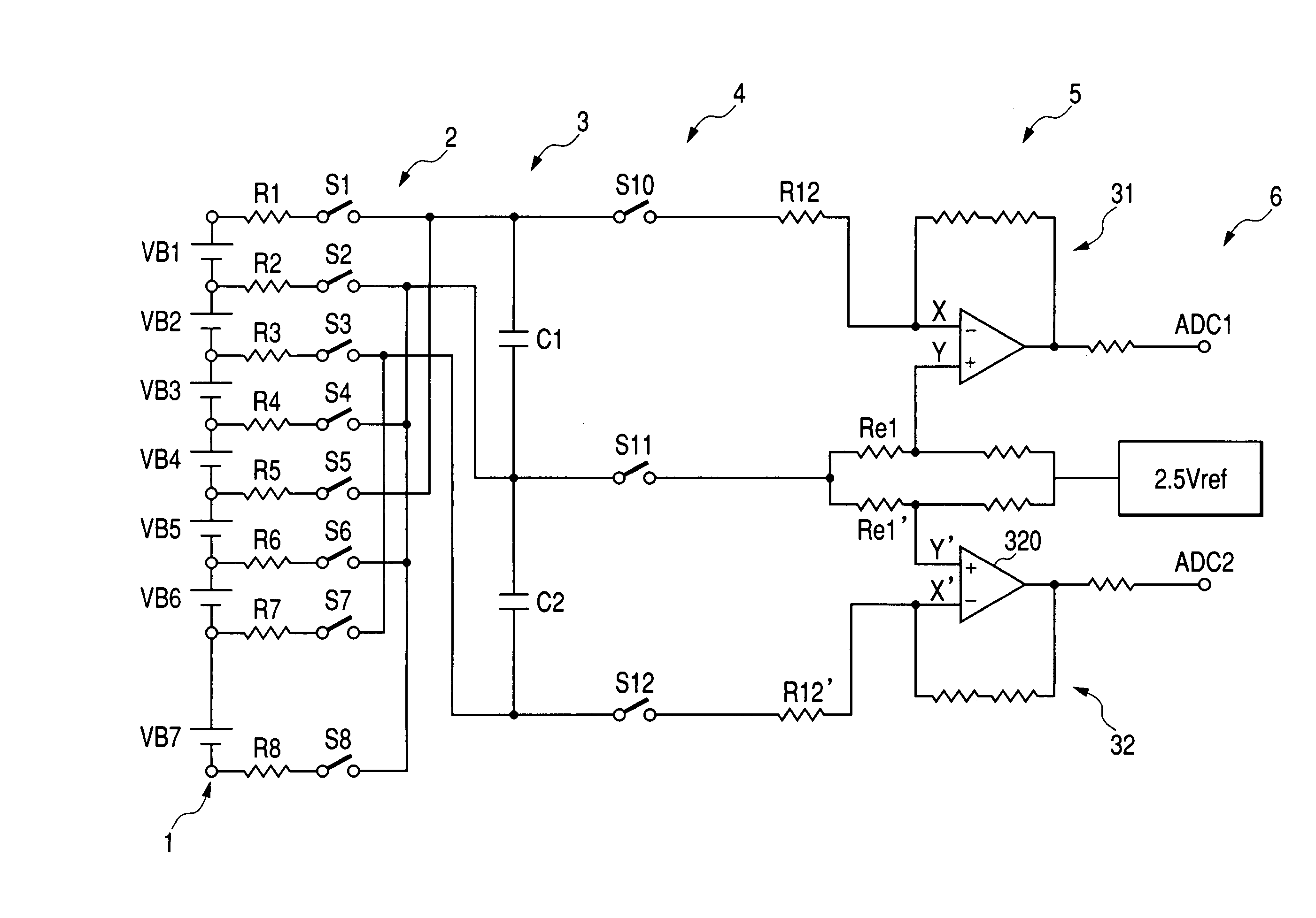
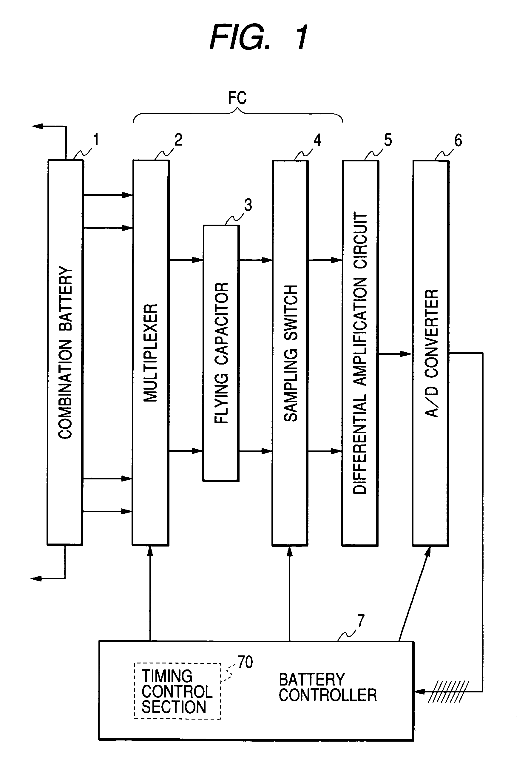
[0041]FIG. 1 shows a circuit block diagram of a voltage detecting apparatus for a combination battery in accordance with a first embodiment of the present invention. The potential difference (i.e., a module voltage) of respective battery modules of a combination battery 1 is successively selected by an input side multiplexer 2 of a flying capacitor voltage detecting circuit FC and is stored in a flying capacitor 3.

[0042]After an arbitrary module voltage is stored into the flying capacitor 3, each sampling switch (i.e., input side sampling switch) of the multiplexer 2 is turned off. The electric potential of the flying capacitor 3 becomes a floating electric potential. Then, an output side sampling switch 4 of the flying capacitor 3 is turned on. The charged voltage of the flying capacitor 3 is applied between a pair of input terminals of a differential amplification circuit 5.

[0043]The differential amplification circuit 5 amplifies an analog input voltage and produces an output supp...

embodiment

Effect of Embodiment

[0064]First, according to the above-described embodiment, as shown in FIG. 3, in the fixed-time routine for the timing table read-in processing and succeeding output of the timing signal, generation of the switching control signal is executed earlier than or prior to generation of the activation signal or the transfer command signal. This arrangement effectively prevents the flying capacitor voltage detection from being delayed, so that the flying capacitor voltage detection can be surely accomplished prior to the A / D conversion or the data transfer. In other words, no adverse influence is given to the later-performed A / D conversion or the data transfer processing. Furthermore, it becomes possible to suppress the fluctuation in the switching pulse width from. Accurately securing the charging time of each capacitor is feasible.

[0065]Namely, in an event that any A / D activation event or any memory storage event coexists with a switch operation event at the same inte...

second embodiment

[0068]FIG. 6 is a flowchart showing the operation in accordance with another embodiment of the present invention.

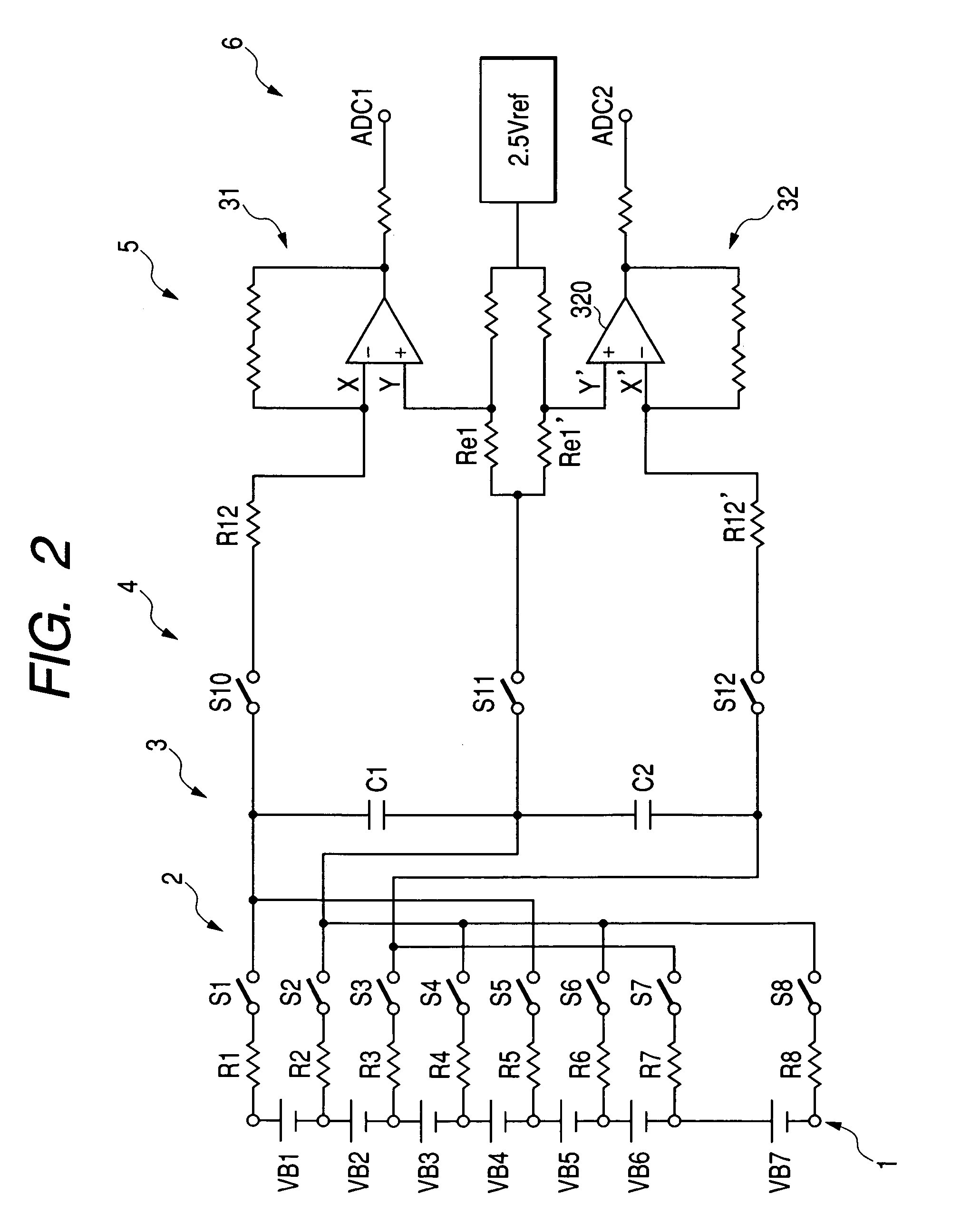
[0069]This embodiment is, in short, characterized in that the next read-out order of module voltages is determined with reference to the largeness of respective module voltages being previously read. To simplify the explanation, this embodiment uses only one flying capacitor. However, it is needless to say that a plurality of flying capacitors can be used as shown in FIG. 2. In this case, each flying capacitor is provided for a group of module voltages and in each group the order of each battery module is determined considering the largeness of the module voltage. The determined order is memorized in the table with the identification number of respective battery modules. And, the next read-out processing is executed based on this table.

[0070]First, the timing control section 70 checks whether or not the read-out processing (including memory storage processing) for all of ...


PUM

PropertyMeasurementUnit
voltageaaaaaaaaaa
digital voltageaaaaaaaaaa
time intervalsaaaaaaaaaa

Abstract

A voltage detecting apparatus for a combination battery includes a multiplexer type flying capacitor voltage detecting circuit, a synchronous control type A/D converter, and a battery controller. The battery controller has a timing table to regulate generation timings of a switching control signal, an activation signal, and a transfer command signal on a common time axis. The timing control is carried out by outputting the switching control signal, the activation signal, and the transfer command signal to the flying capacitor voltage detecting circuit, the A/D converter, and the battery controller at the timing regulated in the timing table and according to an order memorized in the timing table.

Description

BACKGROUND OF THE INVENTION[0001]The present invention relates to a flying capacitor battery voltage detecting apparatus.[0002]A flying capacitor voltage detecting circuit is known as a voltage detecting apparatus preferably applicable to a combination battery which includes a plurality of battery modules, each including a single or a plurality of serially connected cells, which are arranged in series. This flying capacitor voltage detecting circuit performs the voltage read-in processing for sample holding the voltage of a voltage source in a flying capacitor in response to turning-on of an input side sampling switch and the voltage read-out processing for applying a charged voltage of the flying capacitor between a pair of input terminals of a differential amplification circuit by turning on an output side sampling switch after the input side sampling switch is turned off.[0003]Nowadays, a digital signal processing based on a microcomputer or a comparable processor is generally us...

Claims


Application Information

Patent Timeline
Patent Type & Authority Patents(United States)
IPC IPC(8): G01N27/416G01R19/00G01R31/36
CPCG01R31/3658G01R31/362B60L3/0038B60L3/12B60L2240/547B60L2270/147G01R31/396G01R31/3835B60L58/21B60L50/72Y02T10/70Y02T90/40
Inventor FUJITA, HIROSHIKITO, YUJI
Owner DENSO CORP
Why Eureka
Try Eureka