This helps you quickly interpret patents by identifying the three key elements:
Problems solved by technology
Method used
Benefits of technology
[0013]The various embodiments of the invention may provide a number of advantages over the prior art. For example, they may enable the use of a low-voltage, low-cost driver circuit instead of a high-voltage circuit to drive the high-voltage transist
Problems solved by technology
More particularly, these attempts utilized analog modulation schemes that resulted in very low performance applications.
These applications were very complex and costly to implement.
Consequently, these solutions were not widely accepted.
Class D technology was therefore unable to displace legacy Class AB amplifiers in mainstream amplifier applications.
These digital PWM schemes, however, did little to offset the major barriers to integration of PWM modulators into the total amplifier solution.
Class D technology has therefore continued to be unable to displace legacy Class AB amplifiers in mainstream applications.
Th
Method used
Image
Click on the blue label to locate the original text in one second.
Reading with bidirectional positioning of images and text.
Examples
Embodiment Construction
[0022]One or more embodiments of the invention are described below. It should be noted that these and any other embodiments described below are exemplary and are intended to be illustrative of the invention rather than limiting.
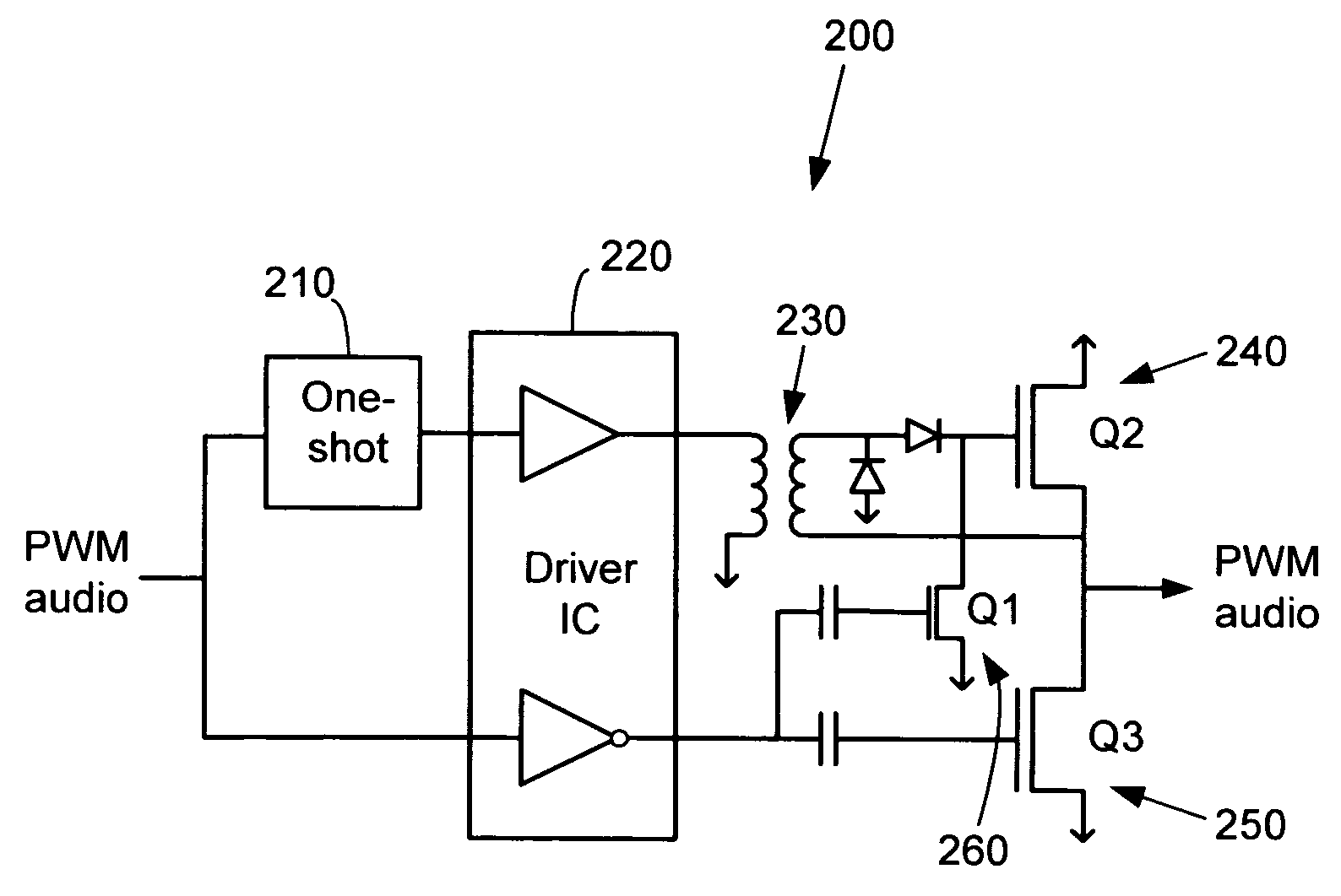
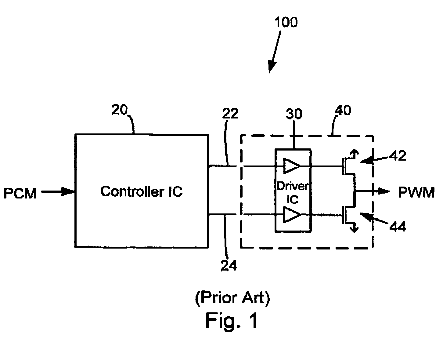
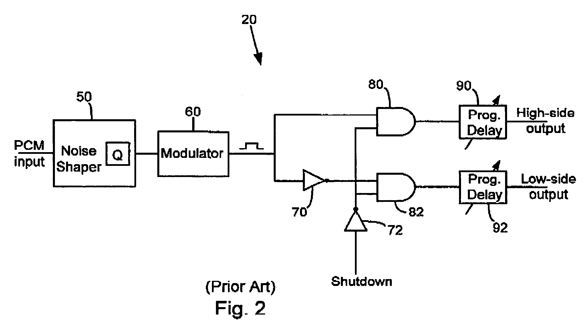
[0023]As described herein, various embodiments of the invention comprise systems and methods for controlling amplification of a pair of pulse width modulated signals. In one embodiment, a system comprises an audio amplifier which is configured to receive a pulse code modulated (PCM) input signal, convert this signal to a pulse width modulated (PWM) signal in a controller, and amplify the PWM signal in an output stage. The controller separates the PWM signal into a high-side signal and a low-side signal. The controller incorporates digitally programmable delays into the processing paths for each of the high-side and low-side signals. The high-side and low-side signals are separately provided to the output stage. The separate high-side and low-side signals can ...
PUM
Abstract
Systems and methods for controlling amplification of a pair of pulse width modulated signals. In one embodiment, a system comprises an audio amplifier which is configured to receive a pulse code modulated (PCM) input signal, convert this signal to a pulse width modulated (PWM) signal in a controller, and amplify the PWM signal in an output stage. The controller separates the PWM signal into a high-side signal and a low-side signal. The controller incorporates digitally programmable delays into the processing paths for each of the high-side and low-side signals. The high-side and low-side signals are separately provided to the output stage. The separate high-side and low-side signals can be used to individually control (e.g., turn off) the high-side and low-side transistors. Circuitry is included to generate a short low-side pulse when both transistors are turned off in order to drain the gate charge from the high-side transistor.
Description
RELATED APPLICATIONS[0001]This application claims priority to: U.S. Provisional Patent Application No. 60 / 469,760, entitled “Integrated PULSHI Mode with Shutdown,” by Andersen, et al., filed May 12, 2003; U.S. Provisional Patent Application No. 60 / 456,414, entitled “Adaptive Anti-Clipping Protection,” by Taylor, et al., filed Mar. 21, 2003; U.S. Provisional Patent Application No. 60 / 456,430, entitled “Frequency Response Correction,” by Taylor, et al., filed Mar. 21, 2003; U.S. Provisional Patent Application No. 60 / 456,429, entitled “High-Efficiency, High-Performance Sample Rate Converter,” by Andersen, et al., filed Mar. 21, 2003; U.S. Provisional Patent Application No. 60 / 456,421, entitled “Output Device Switch Timing Correction,” by Taylor, et al., filed Mar. 21, 2003; U.S. Provisional Patent Application No. 60 / 456,422, entitled “Output Filter, Phase / Timing Correction,” by Taylor, et al., filed Mar. 21, 2003; U.S. Provisional Patent Application No. 60 / 456,428, entitled “Output Fil...
Claims
Application Information
Patent Timeline
Application Date:The date an application was filed.
Publication Date:The date a patent or application was officially published.
First Publication Date:The earliest publication date of a patent with the same application number.
Issue Date:Publication date of the patent grant document.
PCT Entry Date:The Entry date of PCT National Phase.
Estimated Expiry Date:The statutory expiry date of a patent right according to the Patent Law, and it is the longest term of protection that the patent right can achieve without the termination of the patent right due to other reasons(Term extension factor has been taken into account ).
Invalid Date:Actual expiry date is based on effective date or publication date of legal transaction data of invalid patent.