
Multiservice switching system with distributed switch fabric

a switching system and fabric technology, applied in the field of digital telecommunications, can solve the problems of large set of problems at central switching offices, inability to meet the flexibility of delivery timing and order, and place excessive technology burdens, etc., to achieve the effect of increasing volume, increasing traffic throughput, and growing size and speed

Inactive Publication Date: 2006-07-18
MICROSEMI STORAGE SOLUTIONS US INC
View PDF15 Cites 70 Cited by
  • Summary
  • Abstract
  • Description
  • Claims
  • Application Information

AI Technical Summary

Benefits of technology

"The present patent provides a solution for overcoming issues in switch fabric design by allowing for growth in size and speed as traffic throughput increases. It also provides a mechanism for converting traffic between different protocols. The solution includes a distributed switch fabric with a layered structure and interfaces for serialization and error checking. The method involves loading flow content into queues, conducting bidding competitions, and transmitting the results to the switching fabric layer. The technical effects of the patent include improved scalability and flexibility of switch fabrics, as well as improved efficiency and reliability in traffic routing."

Problems solved by technology

There are many other telecommunications protocols for which such flexibilities in delivery timing and order are not acceptable.
The growing popularity of various forms of digitized telecommunication schemes such as ATM, TDM, IP and so forth, can create a large set of problems at central switching offices.
This can place excessive burdens on the technology that is used to implement the switch fabric at the office.
The latter can undesirably push the cost of implementation to unacceptable levels as switching office designers try to keep up with the increasing demands for higher switching bandwidth and the demand for handling different kinds of protocols.
In view of this, the scalability of switching systems becomes an ever-growing problem.
Yet another problem is that of cross-protocol traffic.
Designers of switching office equipment may encounter many difficulties in providing for such multiservice transfers in an economical way.
Yet a further problem is that of bandwidth granularity.
The extra bandwidth is wasted.

Method used


Image

  • Multiservice switching system with distributed switch fabric
  • Multiservice switching system with distributed switch fabric
  • Multiservice switching system with distributed switch fabric

Examples


Embodiment Construction

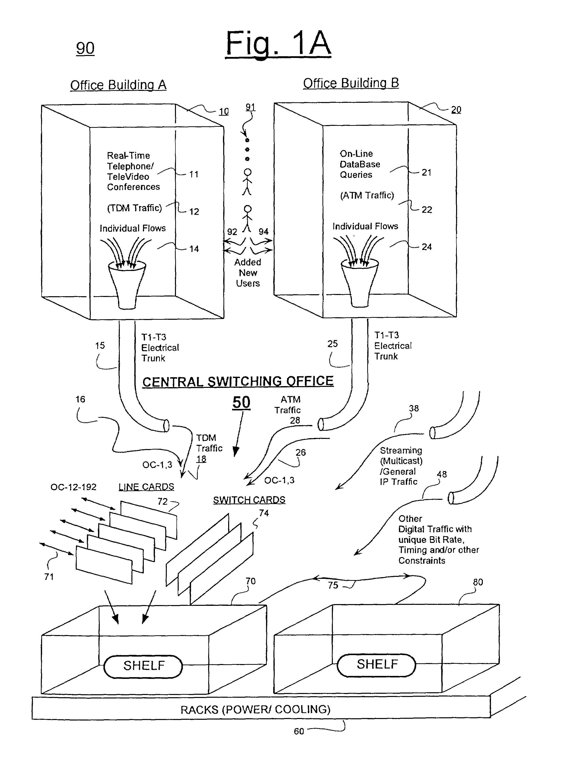
[0042]FIG. 1A is a block diagram of a digital telecommunications environment 90 to which the here disclosed invention may be applied. Environment 90 is assumed to be experiencing usage growth 91 either within one, or more typically among plural ones of different types of digitized telecommunications traffic such as TDM traffic 12 and ATM traffic 22.

[0043]In the illustrated environment 90, a first office building (A) or company campus 10 is assumed to be filled predominantly with digital telephone equipment and / or digital TeleVideo equipment 11. Users 92 of this equipment typically expect their respective telephone or TeleVideo conferences to occur essentially in real time and without perceivable and disruptive breaks of continuity. Because of this, the telecom manager of building / campus 10 has chosen a Time Domain Multiplexing (TDM) protocol 12 as a common exchange scheme for use in the first office building / campus 10. The TDM traffic of building / campus 10 may feed through a corresp...


PUM


Abstract

A digital switching system comprises: (a) a line card layer containing a plurality of real or virtual line cards; (b) a switch card layer containing a plurality of real or virtual switch cards; and (c) an interface layer interposed between the line card layer and the switch card layer for providing serialization support services so that one or more of the line cards and switch cards can be operatively and conveniently disposed in a first shelf or on a first backplane that is spaced apart from a second shelf or from a second backplane supporting others of the line cards and / or switch cards. Such an arrangement allows for scalable expansion of the switching system in terms of number of lines served and / or transmission rates served. The flexibility of the system is owed in part to payload data being carried within payload-carrying regions of so-called ZCell signals as the payload data moves between the line card layer and the switch fabric layer.

Description

CROSS REFERENCE TO CO-OWNED APPLICATIONS[0001]The following copending U.S. patent application is owned by the owner of the present application, and its disclosures is incorporated herein by reference:[0002](A) Ser. No. 09 / 846,875, filed concurrently herewith by Christopher I. W. Norrie, Matthew D. Omes, and Gene K. Chui which is originally entitled, METHOD AND SYSTEM FOR ERROR CORRECTION OVER SERIAL LINK, now U.S. Pat. No. 6,748,567.CROSS REFERENCE TO PATENT PUBLICATIONS[0003]The disclosures of the following U.S. patents are incorporated herein by reference:[0004](A) U.S. Pat. No. 4,486,739, issued Dec. 4, 1984 to Franaszek et al. and entitled “Byte Oriented DC Balanced (0,4) 8B / 10B Partitioned Block Transmission Code”.CROSS REFERENCE TO RELATED OTHER PUBLICATIONS[0005]The following publications are cited here for purposes of reference:[0006](A) CSIX-L1: Common Switch Interface Specification-L1, Published Aug. 5, 2000 as Specification Version: 1.0 at Internet URL: http: / / www.csix.or...

Claims


Application Information

Patent Timeline
Patent Type & Authority Patents(United States)
IPC IPC(8): H04L12/56H04J14/08
CPCH04L49/3045H04L49/45H04L49/201H04L2012/5618H04L49/503H04L49/357
Inventor LAU, ONCHUEN DARYNBERGEN, CHRIS D.DIVIVIER, ROBERT J.CHUI, GENE K.NORRIE, CHRISTOPHER I. W.ORNES, MATTHEW D.CHUI, KING-SHING
Owner MICROSEMI STORAGE SOLUTIONS US INC
Learn More