Maintenance link using active/standby request channels

Inactive Publication Date: 2006-07-18
INTEL CORP
View PDF88 Cites 61 Cited by
  • Summary
  • Abstract
  • Description
  • Claims
  • Application Information

AI Technical Summary

Benefits of technology

[0031]The indication transmitted over the first or second channel in a time slot is analyzed at the receiver to determine the strength of the received signal. If the signal strength is lower than a desired level, a feedback message generated by the receiver is communicated to the transmitter for adjusting its power level for subsequent transmissions on the first or second coded channel. In this way, the power level of a transmitter can be adjusted to reduce co-channel interference in a wireless system. More specifically, the power level of a transmitting device can be gradually increased or decreased so that it has minimal impact on other channels.
[0032]A power adjustment message communicated from the receiver to the transmitter can include a single bit indicating whether the transmitter should increase or decrease its power output for subsequent transmissions. Thus, power can be optimally adjusted even in a dynamic environment where the signal to noise ratio can change almost instantaneously.
[0033]This method of adjusting power is similar to the method as previously described for synchronizing a transmitter to a receiver via feedback messages. However, in this illustrative embodiment, the power level output of the transmitter is adjusted via feedback messages instead of timing. Thus, the power level of a transmitter can be adjusted while in a standby mode so that, in the event that the transmitter goes active transmitting a data payload to the receiver, the power level of the transmitter is optimized to reduce co-channel interference. Both power and timing feedback loops can be implemented simultaneously so that the power output level and timing of a transmitter is optimized for potentially sporadic data transmissions.
[0034]One aspect of the present invention is to provide a link between a base sta

Problems solved by technology

Such services were thought at first to be for the exclusive province of businessmen because of expected high subscriber costs.
There still is no widely available satisfactory solution for providing low cost, high speed access to the Internet, private intranets, and other networks using the existing wireless infrastructure.
First, the typical manner of providing high speed data service in the business environment over a wireline network is not readily adaptable to the voice grade service available in most homes or offices.
For example, such standard high speed data services do not necessarily lend themselves to efficient transmission over standard cellular wireless handsets because wireless net

Method used


Image

  • Maintenance link using active/standby request channels
  • Maintenance link using active/standby request channels
  • Maintenance link using active/standby request channels

Examples


Embodiment Construction

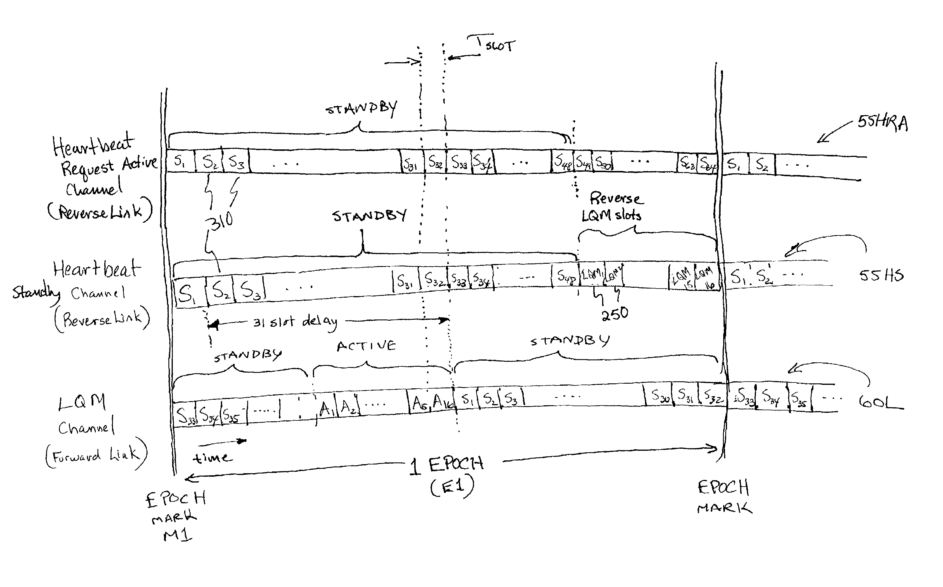
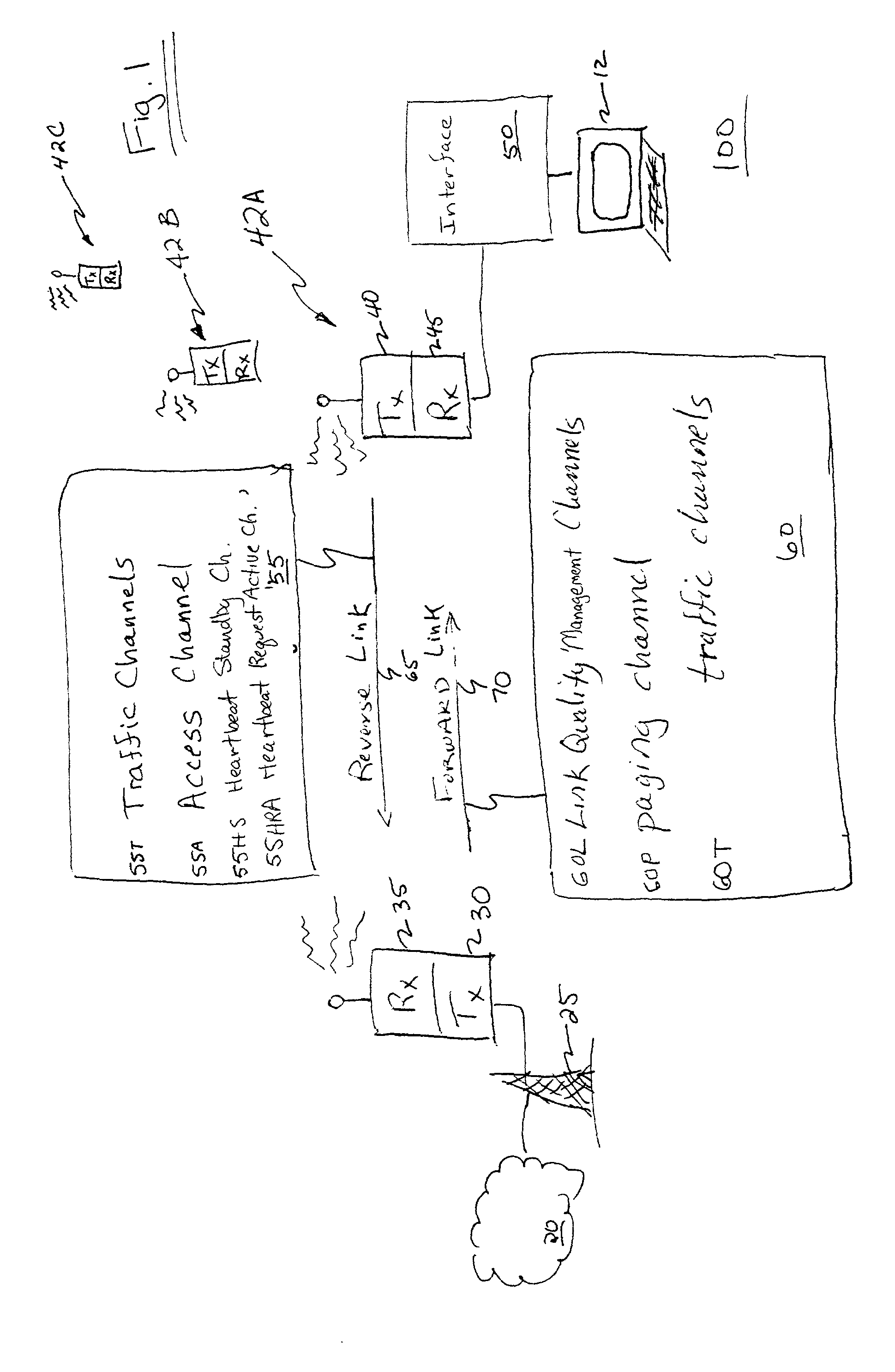
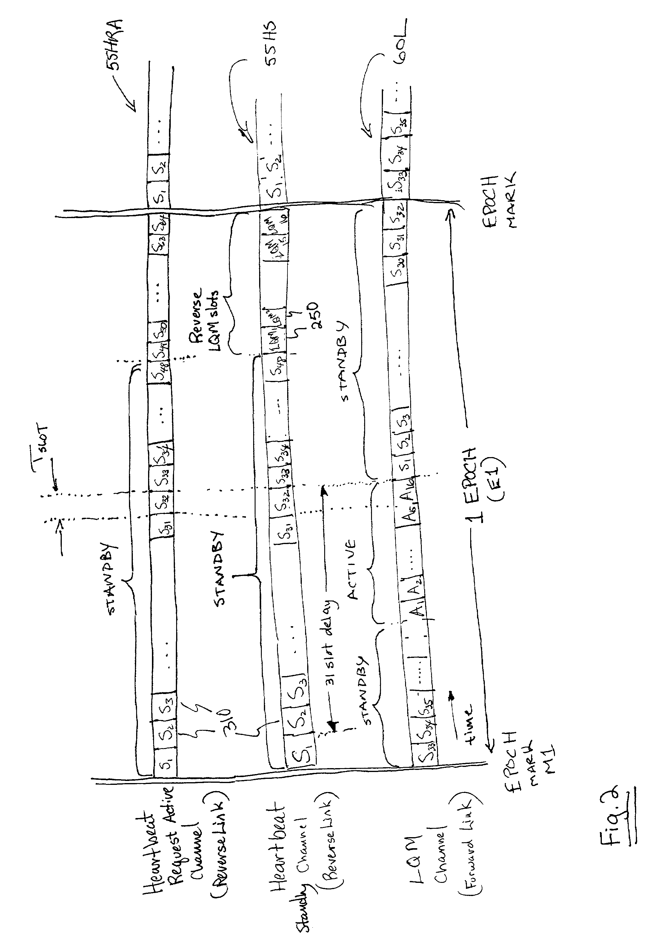
[0045]FIG. 1 is a diagram of a wireless communication system 100 according to the principles of the present invention. A base station 25 maintains wireless communication links with each of a plurality of field units 42A, 42B, 42C (collectively, field units 42) as shown. Such wireless links are established based upon assignment of resources on a forward link 70 and a reverse link 65 between the base station 25 and field units 42. Each link 65 or 70 is typically made up of several logical reverse link channels 55 and several logical forward link channels 60.

[0046]As shown, communication system 100 supports wireless communication between an interface 50 and network 20. Typically, network 20 is a Public Switched Telephone Network (PSTN) or computer network such as the Internet, internet or intranet. Interface 50 is preferably coupled to a digital processing device such as a portable computer 12, to provide wireless access to the network 20. Consequently, portable computer device 12 has ...


PUM


Abstract

Multiple field units in a CDMA system are synchronized for communication with a base station using shared forward and reverse link channels. In an illustrative embodiment, each field unit is assigned a time slot in a forward link channel to receive messages from the base station. Likewise, each field unit is assigned a time slot on a common reverse link channel for transmitting messages to the base station. Timing alignment and power level control among each of many field units and the base station is achieved by analyzing messages received at the base station in a corresponding time slot as transmitted by each field unit. Thereafter, a message is transmitted from the base station in a corresponding time slot to a particular field unit for adjusting its timing or power level so that future messages transmitted from the field unit are received in the appropriate time slot at the base station at a desired power level. In this way, minimal resources are deployed to maintain communication and precise synchronization between a base station and each of multiple users, minimizing collisions between field units transmitting in adjacent time slots on the reverse link. This method reduces the frequency a field unit must rely on the use of a slotted aloha random access channel according to IS-95.

Description

RELATED APPLICATION[0001]This application claims the benefit of U.S. Provisional Application Ser. No. 60 / 180,598 filed on Feb. 7, 2000, the entire teachings of which is incorporated herein by this reference.BACKGROUND OF THE INVENTION[0002]Increasing use of wireless telephones and personal computers has led to a corresponding increase in demand for advanced telecommunication services that were once thought practical only for specialized applications. In the 1980s, wireless voice communication became widely available through cellular telephone networks. Such services were thought at first to be for the exclusive province of businessmen because of expected high subscriber costs. The same was also true for access to remotely distributed computer networks, whereby until very recently, only business people and large institutions could afford the necessary computers and wireline access equipment.[0003]As a result of the widespread availability of affordable new technologies, the general p...

Claims


Application Information

Patent Timeline
IPC IPC(8): H04B7/216G08C17/00H04B7/26H04W56/00
CPCH04W56/0085H04B7/2637
Inventor NELSON, JR., G. RODNEYHOFFMANN, JOHN E.ROUPHAEL, ANTOINE J.PROCTOR, JR., JAMES A.
Owner INTEL CORP
Why Eureka
Try Eureka