Method and circuit for acquisition

a technology of acquisition circuit and acquisition method, which is applied in the direction of synchronization signal speed/phase control, multiplex communication, phase-modulated carrier system, etc., can solve the problems of frame synchronization pattern not being detected correctly, and taking a long time to acquire an rf channel

Inactive Publication Date: 2006-07-18
JVC KENWOOD CORP A CORP OF JAPAN
View PDF5 Cites 29 Cited by
  • Summary
  • Abstract
  • Description
  • Claims
  • Application Information

AI Technical Summary

Benefits of technology

[0083]delay means for delaying eac...

Problems solved by technology

Therefore, if the frequency error contained in the baseband signal is larger than a predetermined value, the frame synchronization pattern cannot be ...

Method used


Image

  • Method and circuit for acquisition
  • Method and circuit for acquisition
  • Method and circuit for acquisition

Examples


first embodiment

[0117]A synchronization acquiring circuit according to the first embodiment of the invention will be described in detail with reference to the accompanying drawings.

[0118]In this synchronization acquiring circuit, an outdoor unit (ODU) or the like down-converts a received radio wave to obtain a broadcasting satellite-intermediate frequency (BS-IF) signal which is quasi-synchronization detected by a quadrature detector to obtain a baseband signal. The baseband signal is quantized for establishing a synchronization.

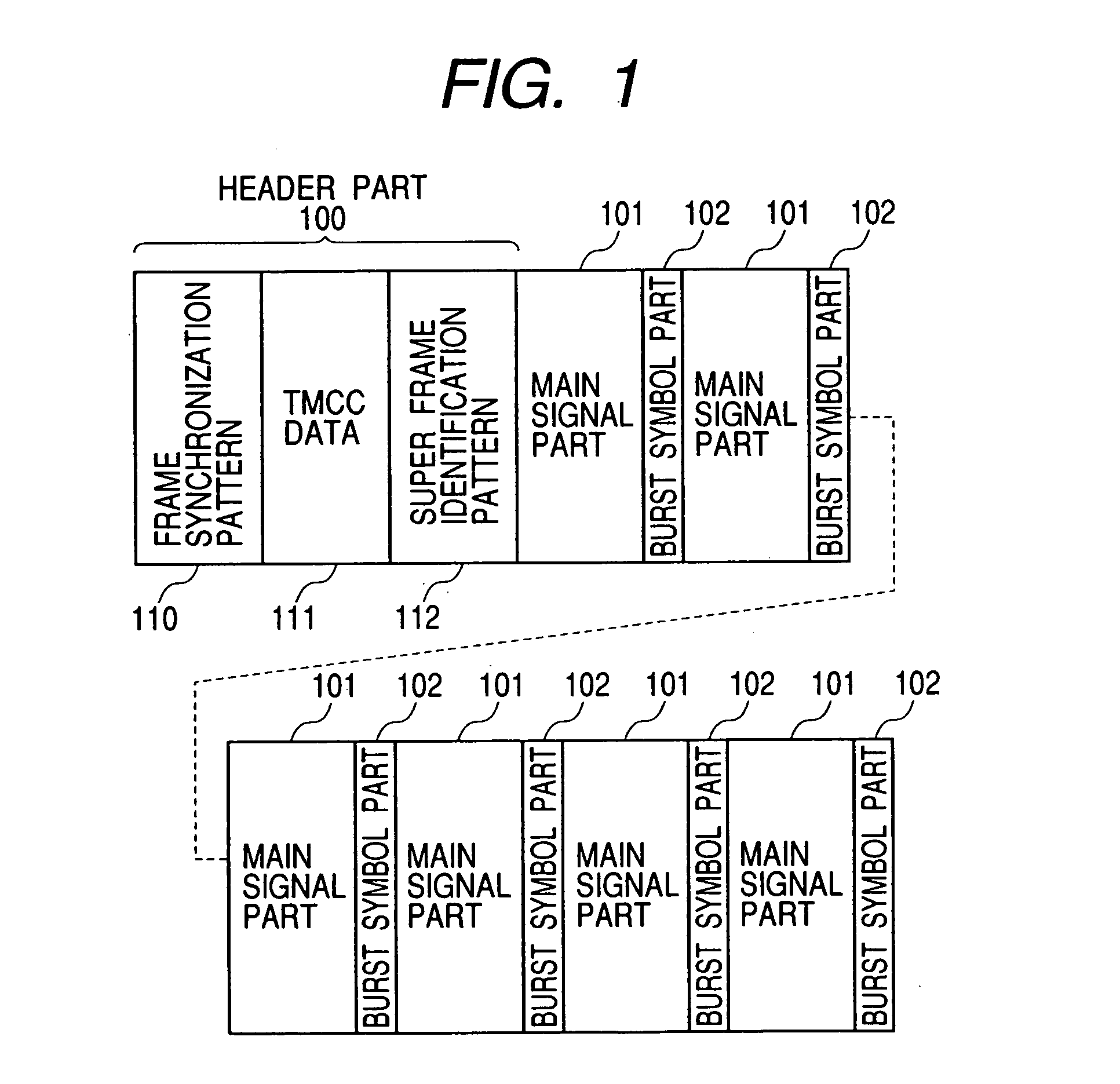
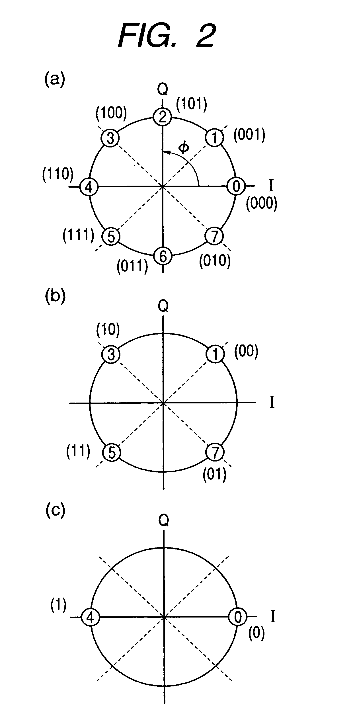
[0119]A baseband signal input to the synchronization acquiring circuit is repetitively transmitted one frame after another after being subjected to a plurality of modulation methods time divisionally used and having different C / N (carrier-to-noise) values required, such as 8PSK (phase shift keying) modulation, QPSK (quadrature PSK) modulation and BPSK (binary PSK) modulation. Such a transmission method is called a hierarchical transmission method.

[0120]FIG. 1 is a diagram s...

second embodiment

[0221]A synchronization acquiring circuit according to the second embodiment of the invention will be described.

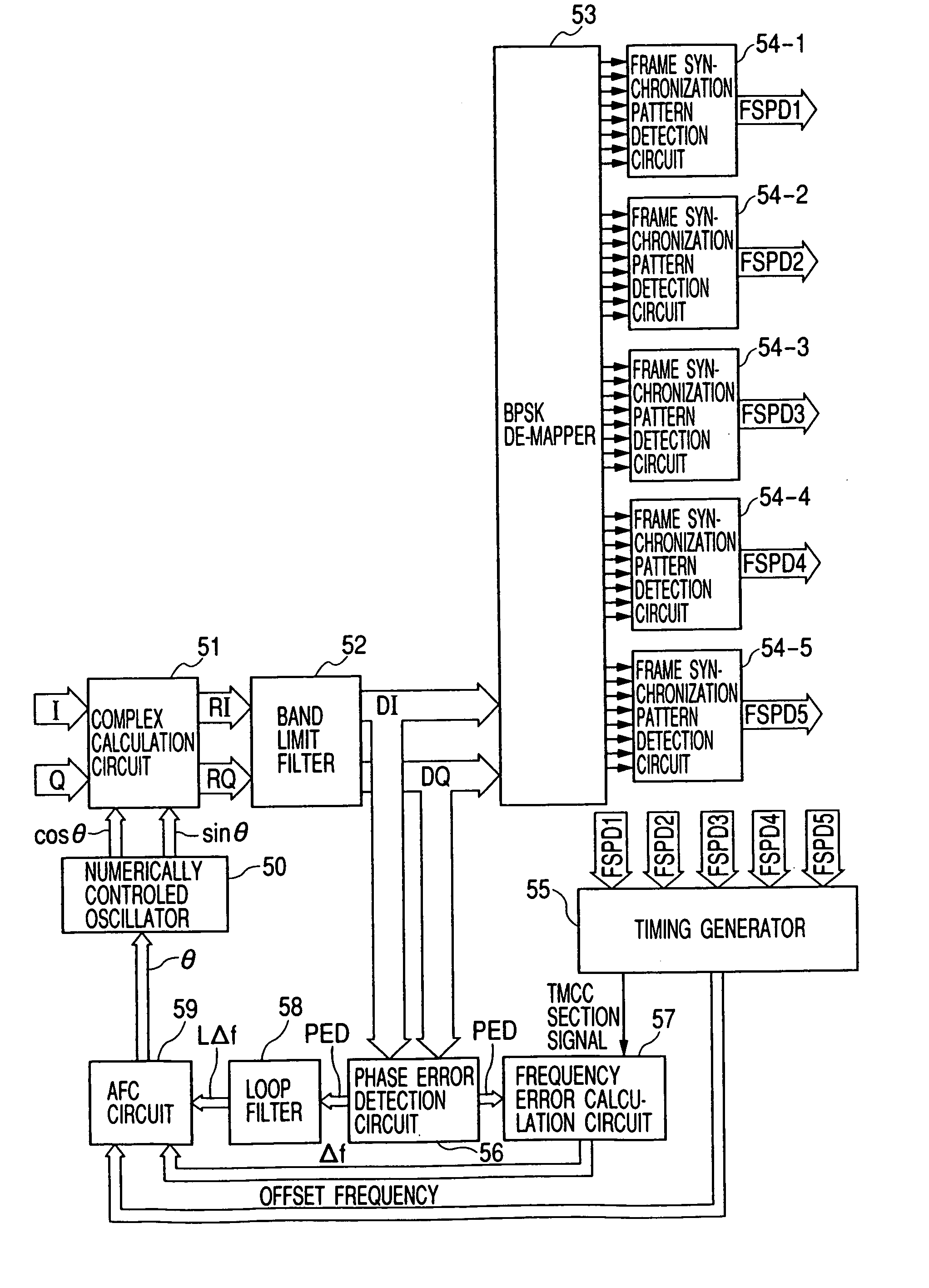
[0222]FIG. 8 shows the structure of the synchronization acquiring circuit according to the second embodiment of the invention.

[0223]As shown in FIG. 8, the synchronization acquiring circuit has a numerically controlled oscillator 50, a complex calculation circuit 51, a band limit filter 52, a BPSK demapper 53, frame synchronization pattern detection circuits 54-1 to 54-5, a timing generator 55, a phase error detection circuit 56, a frequency error calculation circuit 57, a loop filter 58, and an AFC circuit 59.

[0224]The numerically controlled oscillator 50 generates sine wave data sin θ and cosine wave data cos θ respectively. The numerically controlled oscillator 50 generates a digital signal representative of the amplitude of the sine wave data or cosine wave data corresponding to the phase signal θ received from the AFC circuit 59, and sends it to the complex calculatio...


PUM


Abstract

Frame synchronization is quickly established to acquire an RF channel in a short time. Numerically controlled oscillators 1-1 to 1-3, complex calculation circuits 2-1 to 2-3, band limit filters 3-1 to 3-3, a selector 7, a phase error detection circuit 9, a loop filter 10, and an AFC circuit 11 compose a carrier regeneration loop for removing the frequency error of the carrier included in an in-phase component I and a quadrant component Q of the baseband signal input to the complex calculation circuits 2-1 to 2-3. A timing generator 6 detects which of frame synchronization pattern detection circuits 5-1 to 5-3 has detected a frame synchronization pattern, provides the selector 7 with a selection signal corresponding to the decision result, and sends a switch signal to the AFC circuit 11. Thereafter, the carrier for removing the frequency error included in the baseband signal is regenerated to acquire an RF channel in a short time.

Description

FIELD OF THE INVENTION[0001]The present invention relates to a synchronization acquiring circuit for acquiring an RF channel, and more particularly to a synchronization acquiring circuit capable of acquiring an RF channel in a short time.RELATED ART[0002]In receiving digital broadcasting of a broadcasting satellite (BS), a synchronization acquiring circuit such as shown in FIG. 15 is used to establish a synchronization and acquire a radio frequency (RF) channel of a predetermined frequency.[0003]In BS digital broadcasting, a digital signal is transmitted in the frame which is time divisionally divided and multiplexed by various digital modulation methods. In order to acquire an RF channel, it is necessary to detect a frame synchronization pattern and establish a synchronization.[0004]The frame synchronization pattern is formed by a digital signal of symbols transmitted by a BPSK modulation method. In the synchronization acquiring circuit shown in FIG. 15, a BPSK demapper 73 recovers...

Claims


Application Information

Patent Timeline
IPC IPC(8): H04L27/16H04J3/06H04L7/00H04L7/04H04L27/00H04L27/22
CPCH04L7/042H04L27/22H04L2027/0067H04L2027/0057H04L2027/0065H04L2027/003
Inventor SHIRAISHI, KENICHIHORII, AKIHIROMATSUDA, SHOJI
Owner JVC KENWOOD CORP A CORP OF JAPAN
Why Eureka
Try Eureka