Direct conversion of low power high linearity receiver

Inactive Publication Date: 2006-07-18
SONY CORP +1
View PDF52 Cites 25 Cited by
  • Summary
  • Abstract
  • Description
  • Claims
  • Application Information

AI Technical Summary

Benefits of technology

[0014]Thus, there is a need for amplifiers, buffers and other front-end circuits for receivers in which power consumption can be decreased in favorable signal environments without reducing linearity or increasing intermodulation susceptibility in adverse signal environments.

Problems solved by technology

Every electronic circuit is unable to produce outputs larger than some limit.
Every electronic circuit is unable to effectively handle inputs larger than some limit or smaller than some other limit.
If a desired signal and a jamming source at different frequencies are present at the same time (which is typical of the operating environment for radio receivers), then this frequency shift results in cross talk or intermodulation b

Method used


Image

  • Direct conversion of low power high linearity receiver
  • Direct conversion of low power high linearity receiver
  • Direct conversion of low power high linearity receiver

Examples


Embodiment Construction

[0034]Disclosed herein are various alternative embodiments of and alternative designs for the invention. The invention, however, should not be taken as being limited to the embodiments and alternatives described. One skilled in the art will recognize still other alternative embodiments and designs, as well as various changes in form and detail. These may be employed while practicing the invention without departing from its principles, spirit or scope.

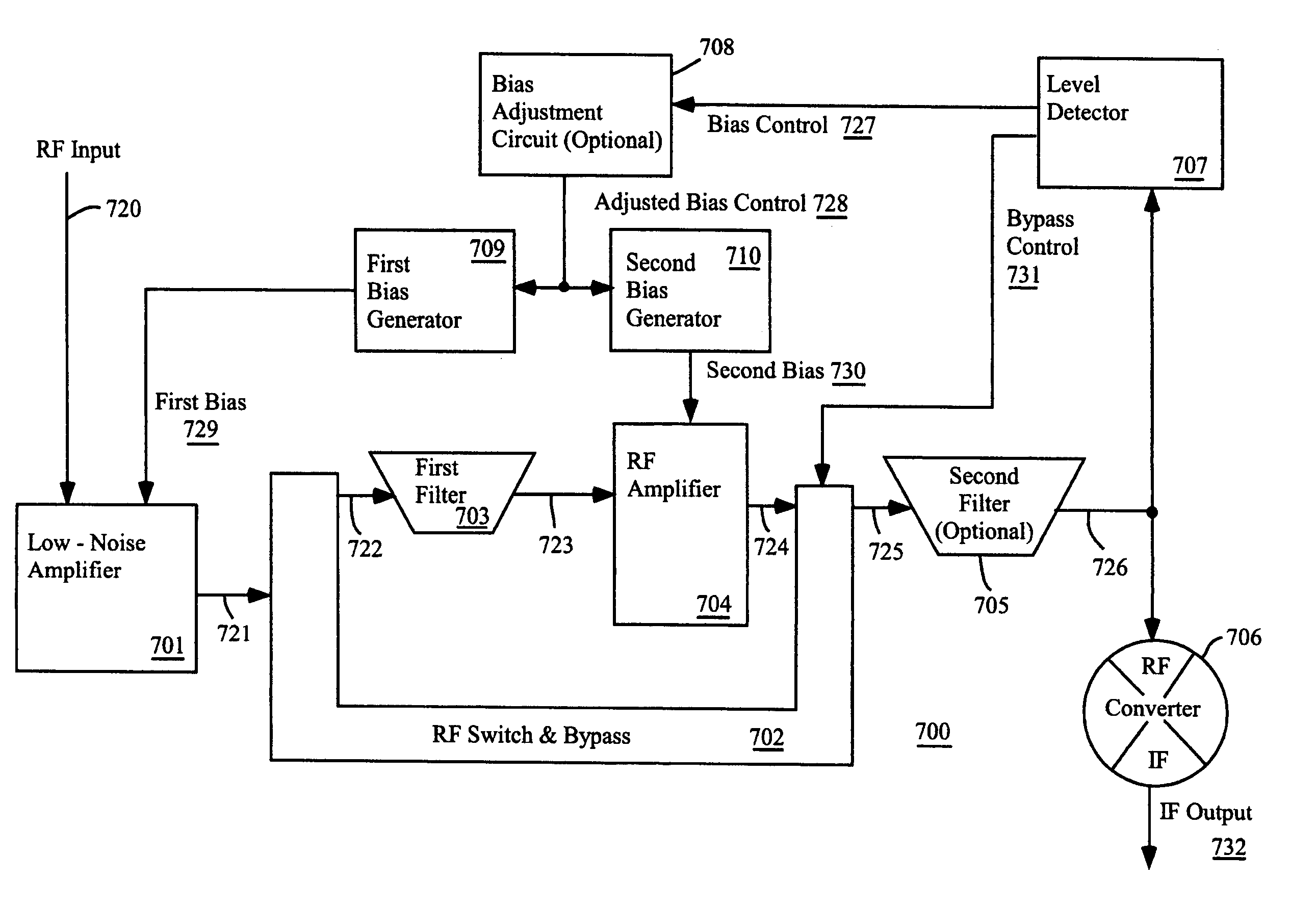
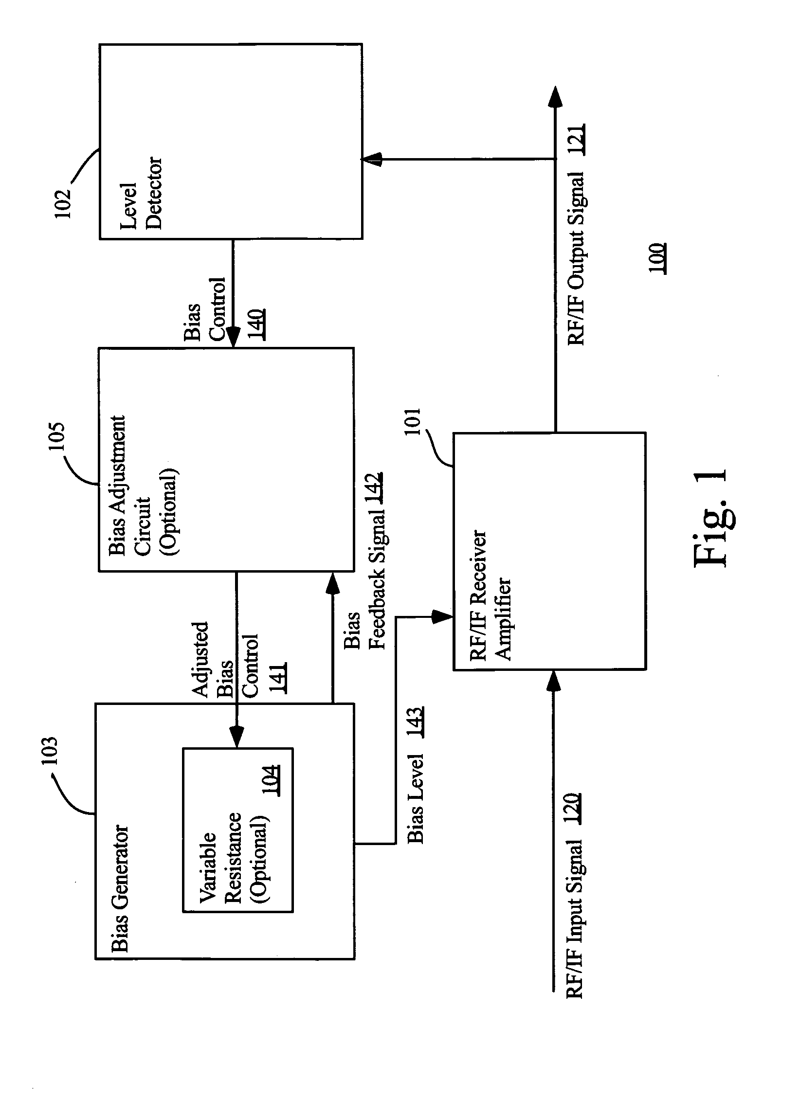
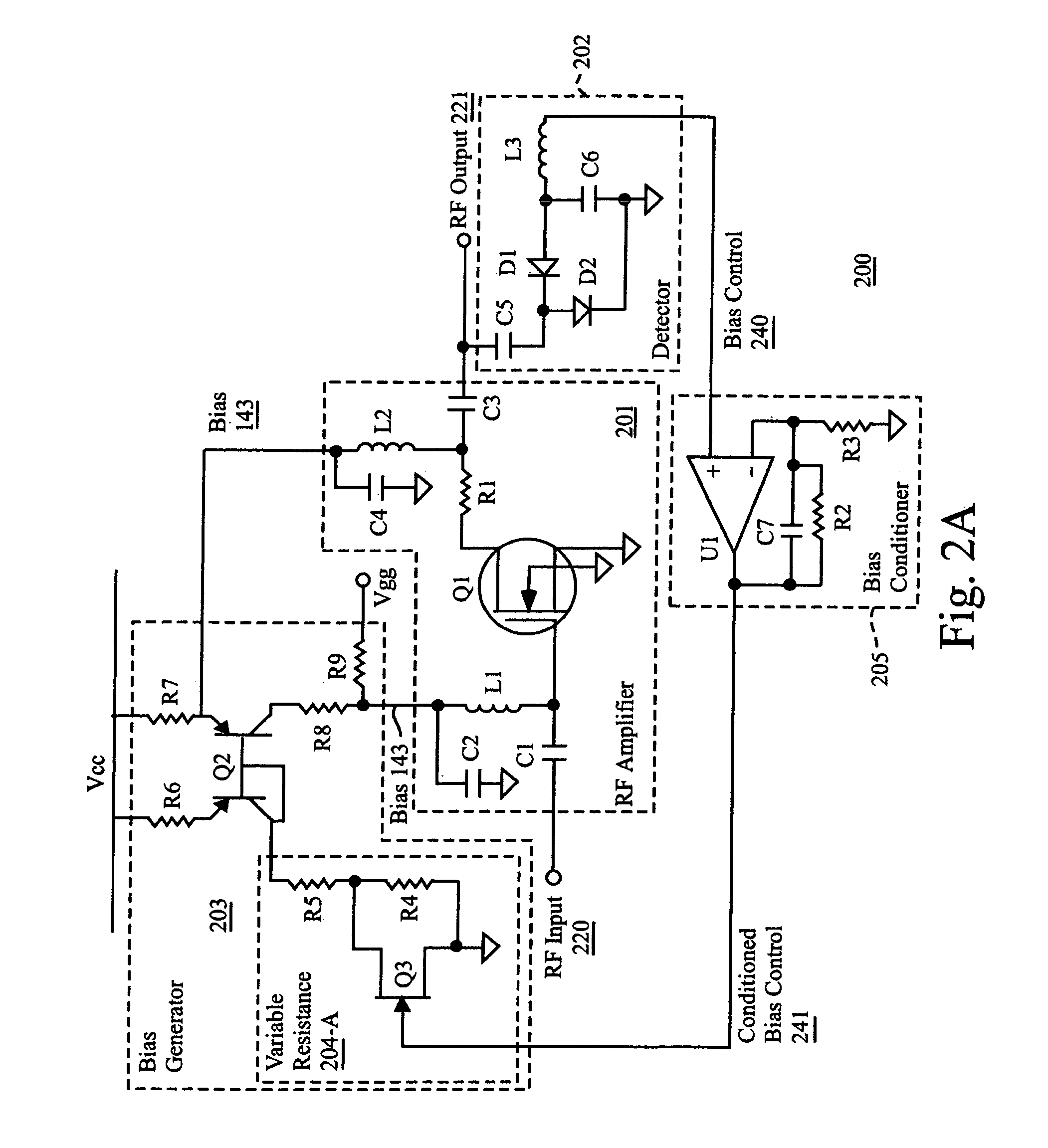
[0035]FIG. 1 is a functional block diagram of receiver amplifier 100 according to one embodiment of the invention. This amplifier has reactive biasing, i.e. it adjusts its bias level in reaction to the signal strength with which it is currently operating.

[0036]RF / IF receiver amplifier 101 amplifies input signal 120 into output signal 121. The bias of amplifier 101 is set by bias level 143, which is produced by bias generator 103.

[0037]RF / IF receiver amplifier 101 can be any type of linear amplifier with characteristics suitable for radi...


PUM


Abstract

A radio frequency receiver includes an amplifier and a detector that produces a bias control signal indicating the level of the signal environment in which the receiver is currently operating. A bias generator sets the bias level of the amplifier according to the bias control signal, where the bias level tends to increase as the signal level increases. Further, the receiver, includes a first circuit adapted to receive a radio frequency input signal, the circuit having an adjustable bias level, a bias control having more than one level of control for generating a bias control signal based upon a base-band signal for controlling the first circuit and generating an output signal; and an alternative bypass switch across the first circuit so as to send a DC signal corresponding to the total power generated by said feedback means.

Description

PRIORITY CLAIM[0001]This application is a continuation of U.S. patent application Ser. No. 10 / 051,250, filed Jan. 18, 2002 now U.S. Pat. No. 6,687,491.FIELD OF THE INVENTION[0002]This invention relates generally to the field of power control for low power high linearity receivers. More particularly, this invention relates to a direct conversion and in particular, it relates to achieving a low power and high linearity receiver by means of reactively adjusting the bias level used by its front-end circuits.BACKGROUND OF THE INVENTION[0003]An electronic amplifier accepts as its input an electronic signal and produces as its output a stronger version of that electronic signal. For example, recording an electrocardiogram on a chart requires amplifying the weak electrical signal produced by a beating heart until the signal is strong enough to move a pen up and down as a paper chart moves past the pen.[0004]A linear amplifier is one in which there is a linear relationship between the electr...

Claims


Application Information

Patent Timeline
IPC IPC(8): H04B1/06H04B7/00H03G3/20H03F1/34H03G3/30H04B1/10H04B1/16H04B1/30
CPCH03F1/3205H04B1/109H03F1/342H03F2200/99H04B1/30
Inventor WIECK, CHRISTOPHER P.
Owner SONY CORP
Why Eureka
Try Eureka