
Arrangement for automated fault detection and fault resolution of a network device

Active Publication Date: 2006-07-18
CISCO TECH INC
View PDF10 Cites 162 Cited by
  • Summary
  • Abstract
  • Description
  • Claims
  • Application Information

AI Technical Summary

Benefits of technology

[0010]There is a need for an arrangement that provides a predictive, reactive and proactive network service that enables network devices to be managed with minimal loss of service.
[0011]There also is a need for an arrangement that enables network device operation to be automatically monitored, where problems associated with the networks device can be anticipated and resolved before encountering a failure in the network device.
[0014]Hence, the supply of selected device state attributes associated with the network event to the rules based troubleshooting system, and the storage of the configuration information for the network device in a database accessible by the troubleshooting, enables the troubleshooting system to precisely identify problem / resolution information, based on the configuration information specifying the precise configuration options (e.g., device model, serial number, hardware and software updates, network topology and configuration, etc.). In addition, more precise problem / resolution information can be added to the databases as additional engineering knowledge is developed for servicing and support of the network devices, along with additional rules that enable the rules based troubleshooting system to determine the optimum problem / resolution information for the network device given its current configurations and current device state attributes.
[0015]Hence, the network based management system provides an arrangement that enables network devices to be automatically monitored and managed to predict problems before they occur, react to detected events within the network device, and provide proactive activities based on updated engineering information added to the databases.

Problems solved by technology

Existing network management and maintenance technology typically requires manual intervention when a network device encounters a failure.
However, as networks and information technology in general become more complex to service and support, the use of a web page based source for troubleshooting information becomes less effective.
In particular a human-web page interface often is inefficient for the network manager, since the network manager often may be required to manually supply device type, serial number, software versions, and a brief statement of the problem in order to provide sufficient search parameters for the web page to generate a query in the back-end databases supported by the vendor.
Unfortunately, such a query fails to take into consideration more complex interactions that may affect the performance of the network device, including network topology, device configurations, and dynamic parameters that affect the network device performance.
In particular, complex networks are composed of multiple network devices that interact between each other.
Moreover, network managers of large networks encounter considerable difficulty in maintaining an accurate inventory of all devices in the network and their respective configurations, including features such as SNMP configuration.
Existing network discovery resources, for example ping sweep resources used to locate IP addresses of SNMP-enabled network devices, are inadequate to provide a comprehensive inventory of the network, since even with existing intelligent device searches, it is almost impossible to maintain an adequate overview of the network to a reasonable, updated status.
Another fundamental problem associated with management of complex networks involves providing hardware or software updates to the network devices as the updates are developed by the device manufacturers.
Although client side resources (i.e., resources executed on a client device) exist that enable a personal computer to search via the Internet for updated revisions for installed software applications, such an arrangement is impractical for network devices such as switches, routers, gateways, etc., that may be installed in a complex network.
Similar problems exist when a network manager may wish to monitor the operational status of a network device: monitoring the operational status of a network device requires adequate configuration of the management features within the device, and of the management station collecting the management data.
Network managers, upon obtaining data that describes the operational status of a network device, are left with the same problem of how to interpret the data describing the device status, in the context of the device operations within the network, and relative to other similar devices having the same configuration and networks having similar network topologies.
Moreover, attempts to contact technical support representatives at a network device manufacturer also may provide limited results, since the technical support personnel do not know exactly what hardware or software features are installed in the customer's network, often causing technical support personnel to suspect that the problem may exist in other devices installed on the network.
Finally, existing network management technology is unable to preempt a network device failure.
For example, if a network device runs low on system resources, typically the reduction in system resources will not be detected with sufficient time to take preventive action, rather, it probably will only be detected once the network device has failed.
Hence, the users of the network having the failed device are unnecessarily burdened with loss of network service.

Method used


Image

  • Arrangement for automated fault detection and fault resolution of a network device
  • Arrangement for automated fault detection and fault resolution of a network device
  • Arrangement for automated fault detection and fault resolution of a network device

Examples


Embodiment Construction

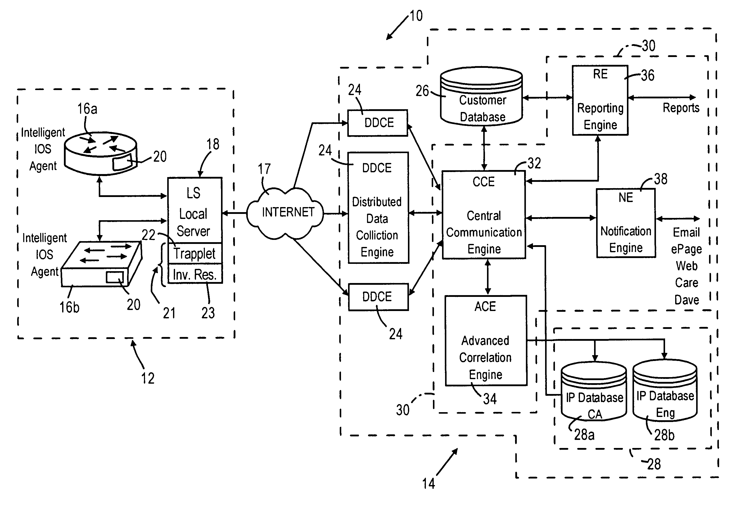
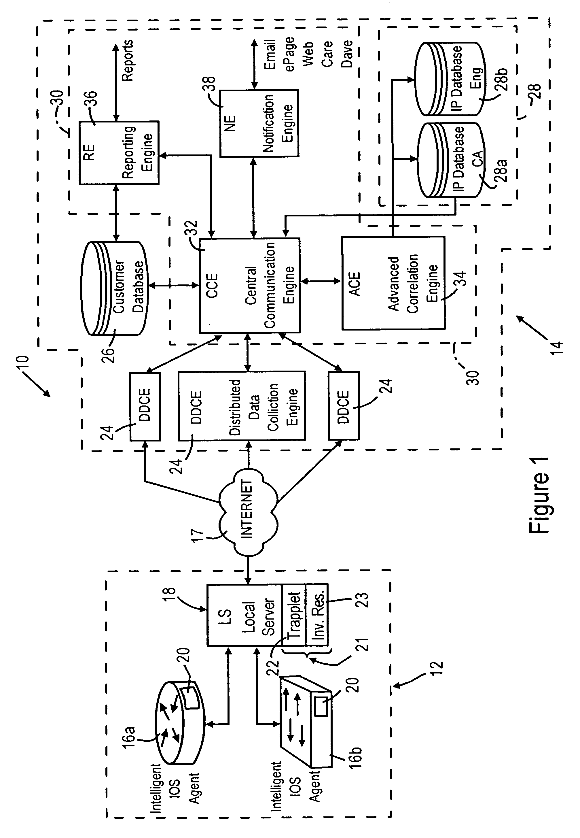
[0025]FIG. 1 is a block diagram illustrating a system 10 for providing automated fault detection and fault resolution in a network, according to an embodiment of the present invention. The system 10 provides automated support services, including predictive health monitoring of network devices, proactive notifications of updated resources and troubleshooting techniques, and automated fault detection and resolution based on detected network device conditions. The system 10 provides automated support services based on coordinated information transfer between customer premises based resources 12, and centralized support resources 14 implemented for example within the device manufacturer's network infrastructure. The information transfer between the customer premises based resources 12 and the centralized support resources 14 is implemented via secure connections via an Internet Protocol (IP) network 17, for example the Internet. Hence, the integration of device and infrastructure inform...


PUM


Abstract

Each network device includes a monitoring agent configured for generating a notification message based upon an event where device operations exceed prescribed monitored parameters. A troubleshooting resource at the customer premises requests selected device state attributes from the network device and that are forwarded to a data collection resource that serves as an interface to the manufacturer's back-end infrastructure. The troubleshooting system accesses databases that store the configuration information for the affected network device, and uses the configuration information for accessing problem / resolution information. The rules based troubleshooting system, upon correlating the databases for the problem / resolution information, provides a service notification message as a response to the event, and selectively includes the problem / resolution information for the network device.

Description

BACKGROUND OF THE INVENTION[0001]1. Field of the Invention[0002]The present invention relates to network management systems, including systems used for systems monitoring, fault detection, troubleshooting, fault resolution, and systems maintenance.[0003]2. Description of the Related Art[0004]Existing network management and maintenance technology typically requires manual intervention when a network device encounters a failure. A network manager, upon isolating the network device having the problem, typically will need to perform a swap of hardware components, or attempt to load updated software in order to attempt to resolve the problem. Almost invariably, however, a network manger will need to obtain additional technical information for managing or to troubleshooting the network device. For example, the network manager may need to access a technical support web page offered by the manufacturers of the network device in order to determine whether “help pages” provide adequate troubl...

Claims


Application Information

Patent Timeline
IPC IPC(8): G06F15/173G06F15/16G06F15/177
CPCG06F11/0709H04L41/064G06F11/079
Inventor BAEKELMANS, JOHNDE KEGEL, ERIKMC DANIEL, DEANSINCLAIR, KEITH
Owner CISCO TECH INC
Learn More