Quick LNG offloading

a technology of lng offloading and lng, applied in the direction of container discharging methods, special purpose vessels, packaged goods, etc., to achieve the effect of low cost and quick receiving of all lng

Active Publication Date: 2006-07-25
SINGLE BUOY MOORINGS INC
View PDF3 Cites 46 Cited by
  • Summary
  • Abstract
  • Description
  • Claims
  • Application Information

AI Technical Summary

Benefits of technology

[0005]In accordance with one embodiment of the invention, applicant constructs the receiving facility at low cost and with the ability to quickly receive all LNG from a tanker. The receiving facility includes a moored floating structure or vessel which can directly receive LNG from a tanker, and which holds a regas unit, a pump unit and crew quarters. The cost for a floating vessel that is moored to the sea floor to weathervane with the tanker and that holds the large amount of equipment, is much less that than of a platform.
[0007]To minimize the tanker rental costs, applicant constructs the vessel with large capacity LNG storage tanks. The storage tanks are large enough to store all LNG offloaded by the tanker, that has not been regassed by the regas unit at the end of offloading. The cost of LNG storage tanks on the vessel is less than the extra charge for tanker rental so the tanker can wait for the LNG being offloaded to be gassed by the regas unit. The cost of LNG storage tanks is also less than the cost for a very large regas unit, which anyway might be prohibited from full operation by environmental laws. However, the regas unit is large enough to heat all offloaded LNG before the tanker next arrives with a load of LNG.

Problems solved by technology

However, the regas unit is large enough to heat all offloaded LNG before the tanker next arrives with a load of LNG.

Method used


Image

  • Quick LNG offloading
  • Quick LNG offloading
  • Quick LNG offloading

Examples


Embodiment Construction

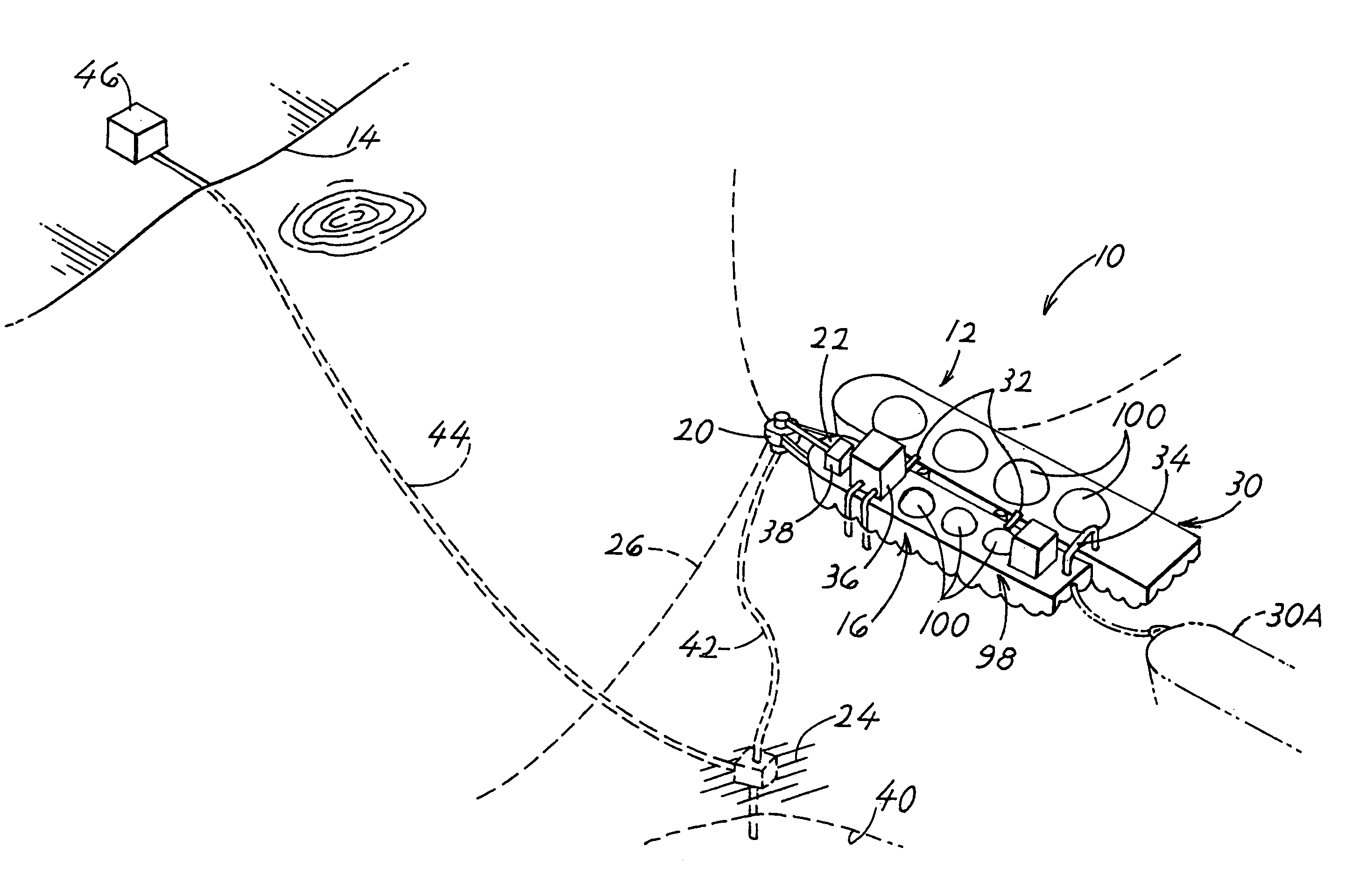
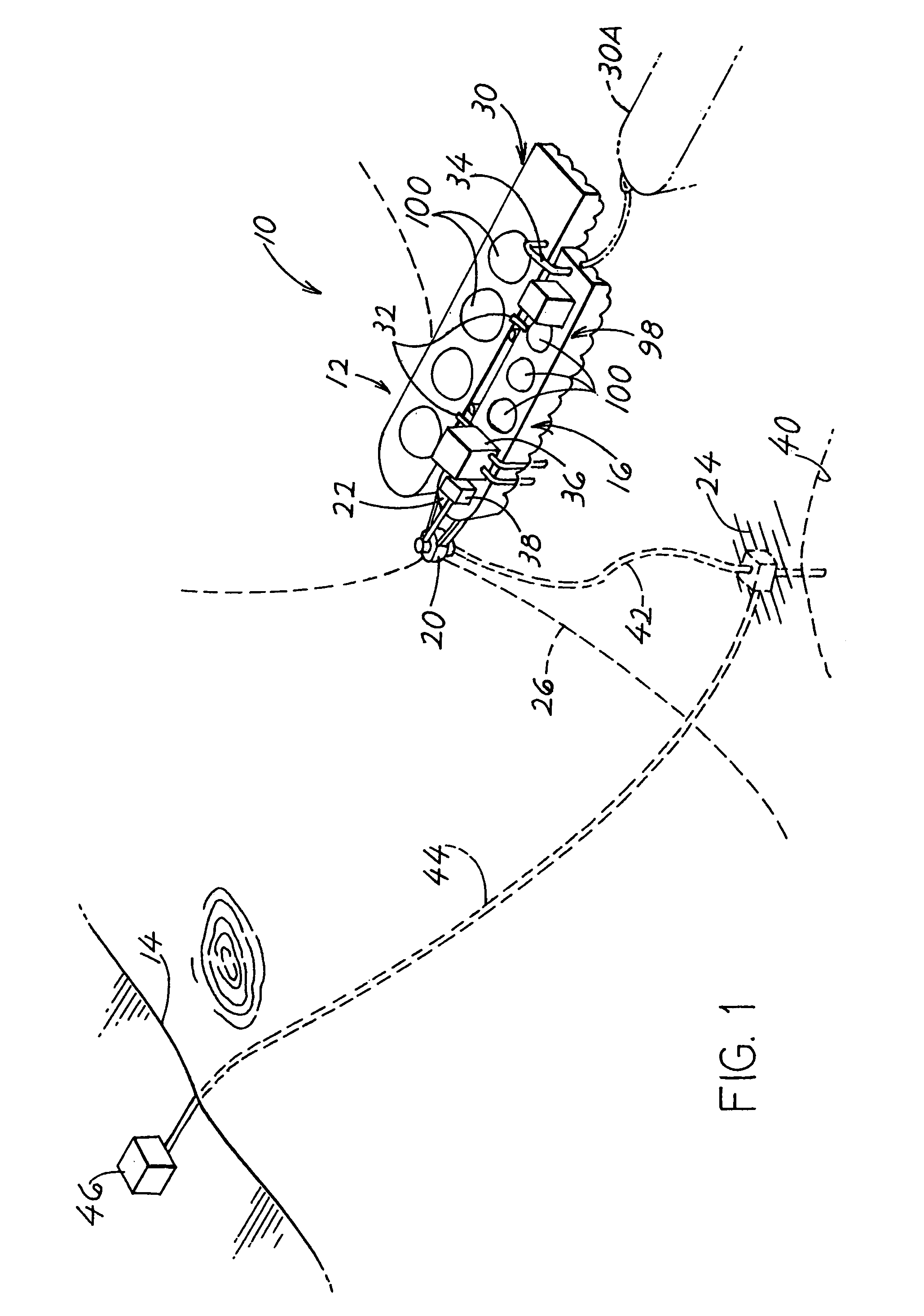
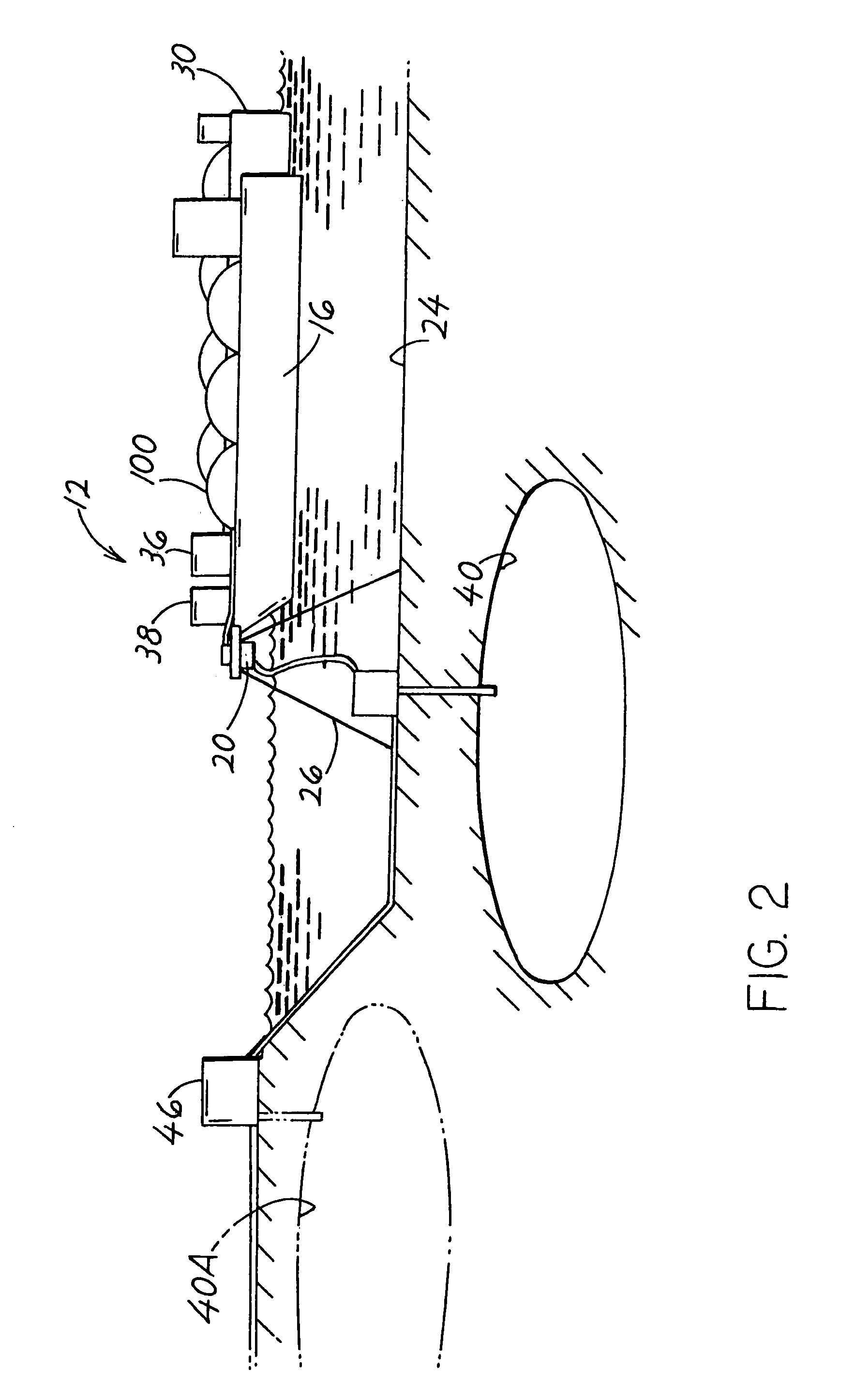
[0014]FIG. 1 illustrates an LNG offloading system 10 of the present invention, which includes an in-sea structure 12 that lies in the sea and away from the shore 14. The in-sea structure comprises a floating and weathervaning vessel or other floating structure 16 such as in the form of a barge with a turret 20 at or near the vessel bow 22. The barge or other floating structure, is moored to the sea floor 24 by catenary chains 26 that extend in catenary curves to the sea floor and then along the sea floor to an anchor. A tanker 30 that carries LNG (liquified natural gas) is moored to the floating structure as by mooring elements 32, so the tanker weathervanes with the barge. FIG. 1 shows two moored tanker positions at 30 and 30A. An LNG transfer unit 34 which may include a hose and pump or a loading arm, offloads the LNG from the tanker. The floating structure 16 carries a regas system or unit 36 that heats LNG to turn it into gas, and that also carries an injection or pump unit 38 t...


PUM

PropertyMeasurementUnit
temperatureaaaaaaaaaa
temperaturesaaaaaaaaaa
temperatureaaaaaaaaaa

Abstract

A system of the type wherein LNG from a tanker (30) is offloaded to a moored vessel (16), which has a regas unit (36) which heats the LNG to transform it into gaseous hydrocarbons, and which has a pump unit (38) that pumps the gaseous hydrocarbons to a consumer (46) such as an onshore gas distribution facility. The system is constructed to enable more rapid tanker unloading so the tanker is released earlier to sail back to a pickup location. The moored vessel has a thermally insulated LNG storage facility such as LNG tanks (100), with a capacity to store all LNG not regassed during offloading of the tanker. The regas unit has sufficient capacity to regas all LNG received in one tanker load, before the tanker returns with another load of LNG.

Description

CROSS-REFERENCE[0001]Applicant claims priority from U.S. provisional application Ser. No. 60 / 566,680 filed Apr. 30, 2004.BACKGROUND OF THE INVENTION[0002]Gaseous hydrocarbons, which are hydrocarbons that are gaseous at mild environmental temperatures such as 20° C. and atmospheric pressure, are often transported great distances by tanker in liquid form as LNG (liquified natural gas). To keep the gas liquid, it is stored on the tanker at a low temperature such as −160° C. in highly thermally insulated tanks. At the tanker offloading destination, the LNG is offloaded to a receiving station where it is regassed (heated to turn it into a gas) and stored for later use.[0003]Proposed prior art offloading stations include a large fixed platform extending up from the sea floor to a height above the sea surface. Such platform would contain a heating system that regassed the LNG, a pump system that pressurizes the gas, and crew quarters or other crew facilities. The regas unit or system must ...

Claims


Application Information

Patent Timeline
Patent Type & Authority Patents(United States)
IPC IPC(8): B65B1/04F17C5/06F17C9/02F17C13/02
CPCF17C5/06F17C13/02F17C9/02F17C2270/0163F17C2221/033F17C2223/0161F17C2223/033F17C2225/0123F17C2225/035F17C2227/0135F17C2227/0302F17C2227/0393F17C2250/0426F17C2260/025F17C2265/05F17C2270/0105F17C2270/0113F17C2270/0123F17C2270/0142F17C2270/016B63B27/34
Inventor POLLACK, JACKWILLE, HEIN
Owner SINGLE BUOY MOORINGS INC
Why Eureka
Try Eureka