Microfluidic pumps and mixers driven by induced-charge electro-osmosis

a microfluidic pump and electro-osmosis technology, applied in the field of microfluidics, micrototalanalysis systems (tas), microelectromechanical systems, can solve the problems of irreversible failure, microfluidic devices employing dc electric fields, and typically take from seconds to minutes,

Inactive Publication Date: 2006-07-25
MASSACHUSETTS INST OF TECH
View PDF15 Cites 70 Cited by
  • Summary
  • Abstract
  • Description
  • Claims
  • Application Information

AI Technical Summary

Benefits of technology

[0012]According to one aspect of the invention, there is provided a microfluidic device. The microfluidic device includes one or more microchannels providing a passageway for transmitting an electrolyte fluid. A field source provides a defined field in the one or more microchannels, wh

Problems solved by technology

This typically takes from seconds to minutes—far too slow for envisioned applications.
In spite of its appealing simplicity, however, there are several drawbacks to the use of DC electric fields, related to the fact that a steady current ({right arrow over (J)}=σ{right arrow over (E)}) must exist in order to maintain a steady field because every electrolyte has a non-negligible bulk conductivity.
This can cause a variety of problems.
For example, the dissolution of the anode eventually destroys the electric circuit, causing irreversible failure.
Microfluidic devices employing DC electric fields thus typically have short lifetimes, which can be acceptable in some applications, such as one-time drug delivery, but not in others, such as μTAS.
A shorter lifetime also translates into a higher cost per unit of time of operation.
The dissolution of the anode also injects metallic ions into the fluid, which can present safety hazards in biomedical applications or can interfere with chemical reactions in μTAS.
Also, the depositions of ions at the ca

Method used


Image

  • Microfluidic pumps and mixers driven by induced-charge electro-osmosis
  • Microfluidic pumps and mixers driven by induced-charge electro-osmosis
  • Microfluidic pumps and mixers driven by induced-charge electro-osmosis

Examples


Embodiment Construction

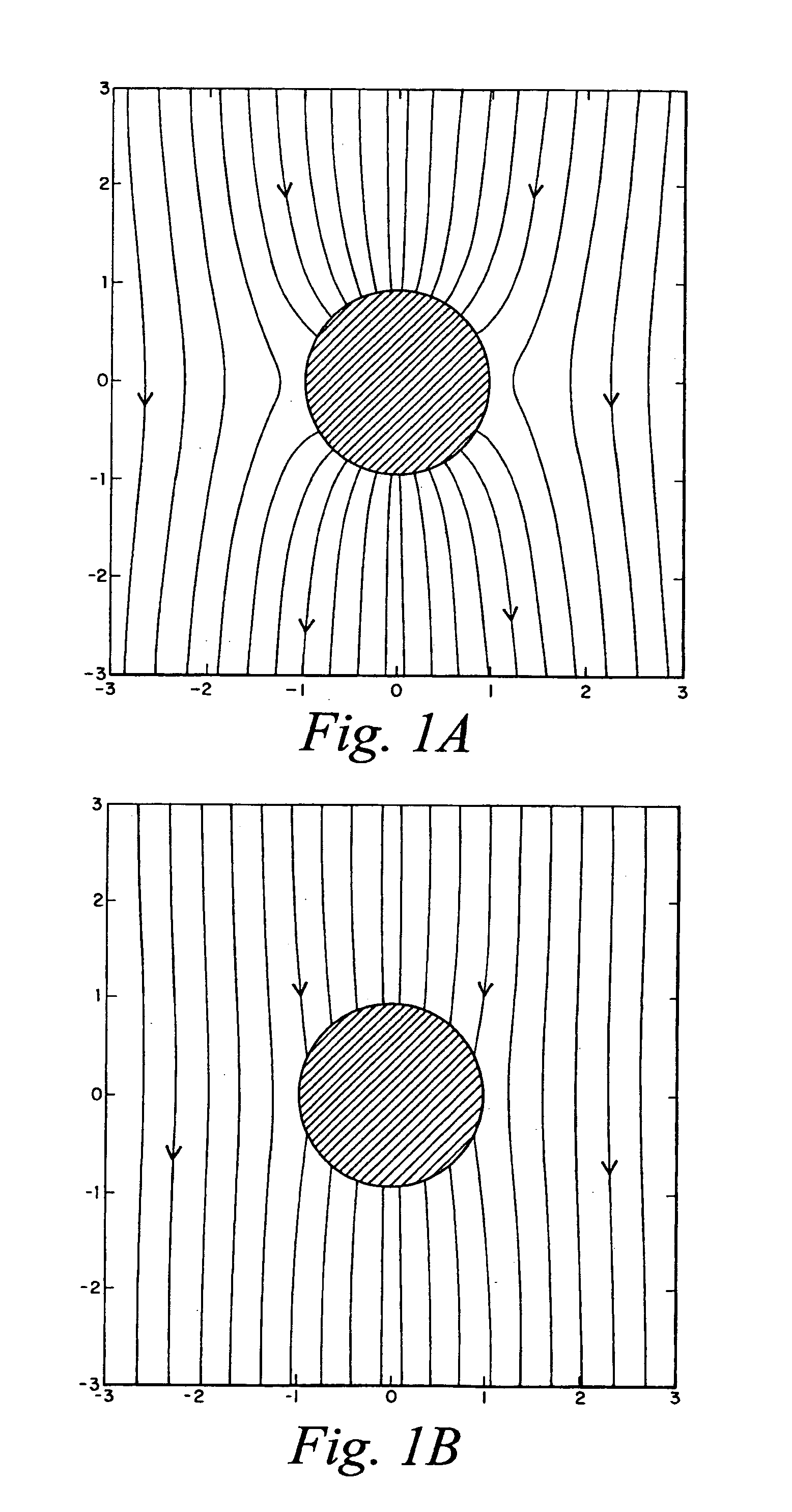
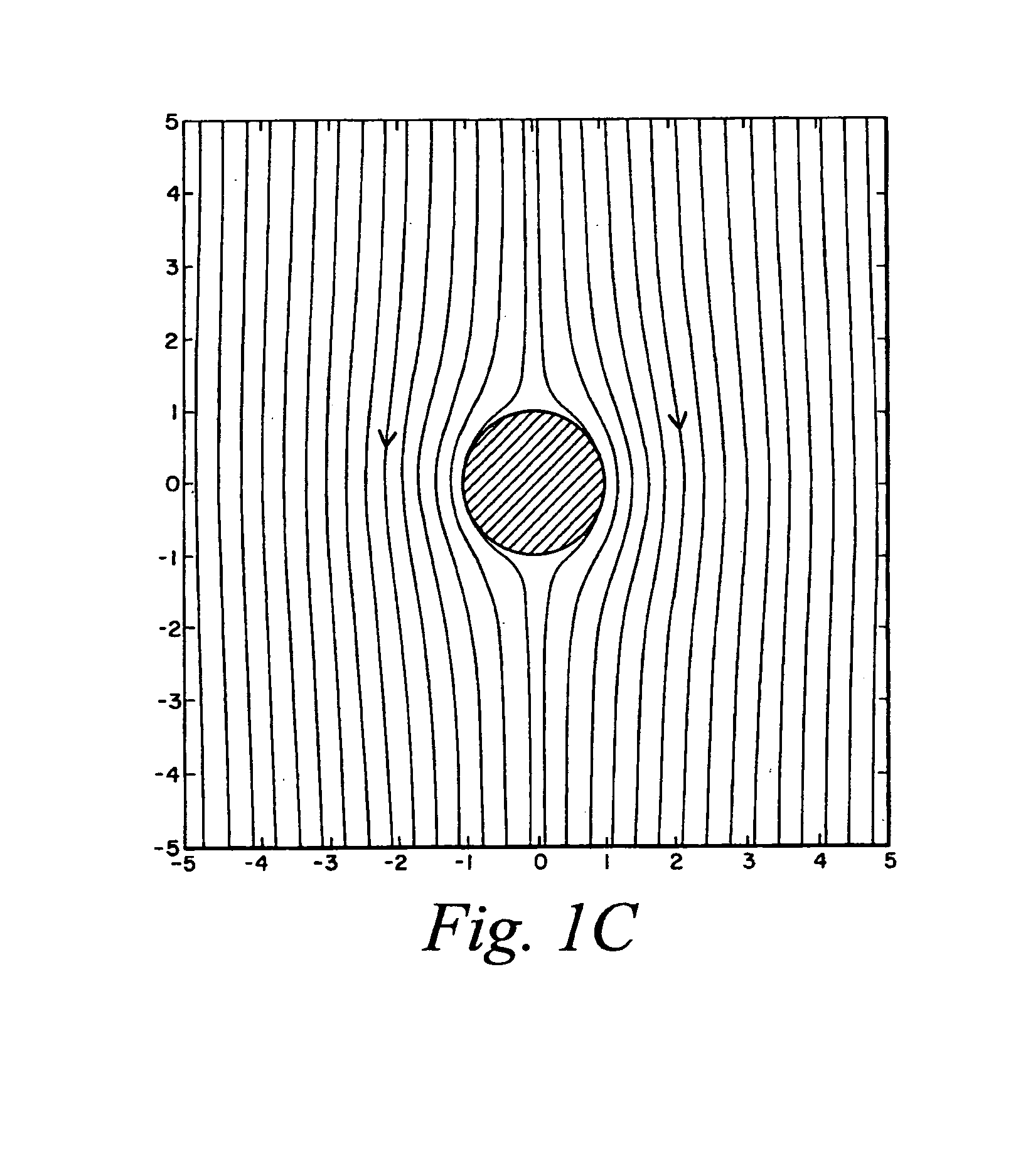
[0022]FIGS. 1A–1C are schematics of the evolution of an electric field around a solid conducting cylinder immersed in a liquid electrolyte, which illustrates the basic physical mechanisms underlying this invention. Just after an electric field is applied, it must intersect a conducting surface at right angles, as shown in FIG. 1A. Mobile ions in the liquid electrolyte are driven along electric field lines—positive ions in the direction of the field, and negative ions opposite the field direction. At the conductor / electrode surface, the field lines terminate, causing ions to accumulate in a small ‘diffuse layer’ and inducing an opposite ‘image charge’ in the conductor. From the geometry of the field lines, one can see that positive ions accumulate around the side of the conductor nearest the field source, on the top half of the cylinder in FIGS. 1A–1C, and negative ions around the side nearest the field sink. This induced-charge ‘diffuse layer’ grows, gradually expelling field lines,...


PUM

PropertyMeasurementUnit
Flow rateaaaaaaaaaa
Polarityaaaaaaaaaa
Radiusaaaaaaaaaa

Abstract

A microfluidic device includes one or more microchannels providing a passageway for transmitting an electrolyte fluid. A field source provides a defined field in the one or more microchannels, wherein at least one conductor element that is placed in at least one specific location in the device. Interactions between the defined field and the at least one conductor element produce electro-osmotic flows so that the electrolyte fluid is driven across the one or more microchannels.

Description

PRIORITY INFORMATION[0001]This application claims priority from provisional application Ser. No. 60 / 341,777 filed Dec. 18, 2001.BACKGROUND OF THE INVENTION[0002]The invention relates to the fields of microfluidics, micro-total-analysis systems (μTAS) and micro-electro-mechanical systems (MEMS), in particular microfluidic pumps and mixers driven by induced-charge electro-osmosis.[0003]The ability to transport fluids in micron-sized channels is essential for many emerging technologies, such as in vivo drug delivery devices, micro-electro-mechanical systems (MEMS), and micro-total-analysis systems (μTAS). New methods for the rapid mixing of inhomogeneous fluids in micron-scale devices are also required, since the absence of turbulent mixing on these small length scales implies that mixing occurs by molecular diffusion alone. This typically takes from seconds to minutes—far too slow for envisioned applications. New technologies are thus required for the manipulation, transport and mixin...

Claims


Application Information

Patent Timeline
IPC IPC(8): G01N27/26B01D61/56F04B17/00F04B19/00
CPCB01D61/56F04B19/006F04B17/00
Inventor SQUIRES, TODD M.BAZANT, MARTIN Z.
Owner MASSACHUSETTS INST OF TECH
Why Eureka
Try Eureka