Method for protection of adhesives used to secure optics from ultra-violet light

a technology of ultraviolet light and adhesives, applied in the field of optical elements, can solve the problems of reducing the performance or even failure deteriorating the adhesive, and reducing the performance of the optical system, so as to reduce the amount of scattered light emitted

Inactive Publication Date: 2006-07-25
ASML HLDG NV
View PDF22 Cites 29 Cited by
  • Summary
  • Abstract
  • Description
  • Claims
  • Application Information

AI Technical Summary

Benefits of technology

[0009]The present invention is directed to a method for reducing the amount of scattered light emitted through an optical element to protect an adhesive used to hold the optical element in place from light induced deterioration. The method includes applying a thin coating of an organoxy-metallic compound to points on an optical element where adhesive will be applied and curing the organoxy-metallic compound to leave behind an optically inert, light absorbing metal oxide film on the points on the optical element where adhesive will be applied.
[0011]Treatment of an optical element using the current invention provides two principal benefits. First, applying the light absorbing coating to an optical element using the current invention reduces the light-induced deterioration of an adhesive used to hold an optical element in place. Ordinarily, ultra-violet light will be internally scattered and propagated to points on an optical element where adhesive has been applied. The light emitted will impinge upon the adhesive resulting in deterioration of the adhesive. The adhesive deterioration will enable potential movement of the optical element leading to reduced performance or even failure of the optical system. The present invention will prevent the adhesive deterioration and resulting undesirable affects.
[0012]Second, the present invention leads to a reduction in out-gassing as compared to conventional mounting techniques using an adhesive. When ultra-violet light impinges upon an adhesive, the adhesive will emit gasses that may produce a thin film residue on the polished surfaces of an optical element leading to reduced performance of the optical system. Once again, the present invention will reduce out-gassing from the adhesive and the resulting undesirable affects.
[0014]Even assuming that existing systems could be modified to apply a thin coating to points on an optical element where adhesive would be applied, the present invention offers additional advantages. Existing systems used to apply thin coatings to polished optical surfaces are designed to apply a coating with a very precise thickness. Such precision is not necessary when applying a coating to an optical element to prevent light from impinging upon adhesive holding an optical element in place. Thus, using modified current coating systems would be more expensive and time consuming than the use of the current invention because of the system setup time needed and the additional complexities associated with working with systems designed to be very precise.

Problems solved by technology

The light emitted will impinge upon the adhesive resulting in deterioration of the adhesive.
The adhesive deterioration will enable potential movement of the optical element leading to reduced performance or even failure of the optical system.
When ultra-violet light impinges upon an adhesive, the adhesive will emit gasses that may produce a thin film residue on the polished surfaces of an optical element leading to reduced performance of the optical system.

Method used


Image

  • Method for protection of adhesives used to secure optics from ultra-violet light
  • Method for protection of adhesives used to secure optics from ultra-violet light
  • Method for protection of adhesives used to secure optics from ultra-violet light

Examples


Embodiment Construction

[0023]While the present invention is described herein with reference to illustrative embodiments for particular applications, it should be understood that the invention is not limited thereto. Those skilled in the art with access to the teachings provided herein will recognize additional modifications, applications, and embodiments within the scope thereof and additional fields in which the present invention would be of significant utility.

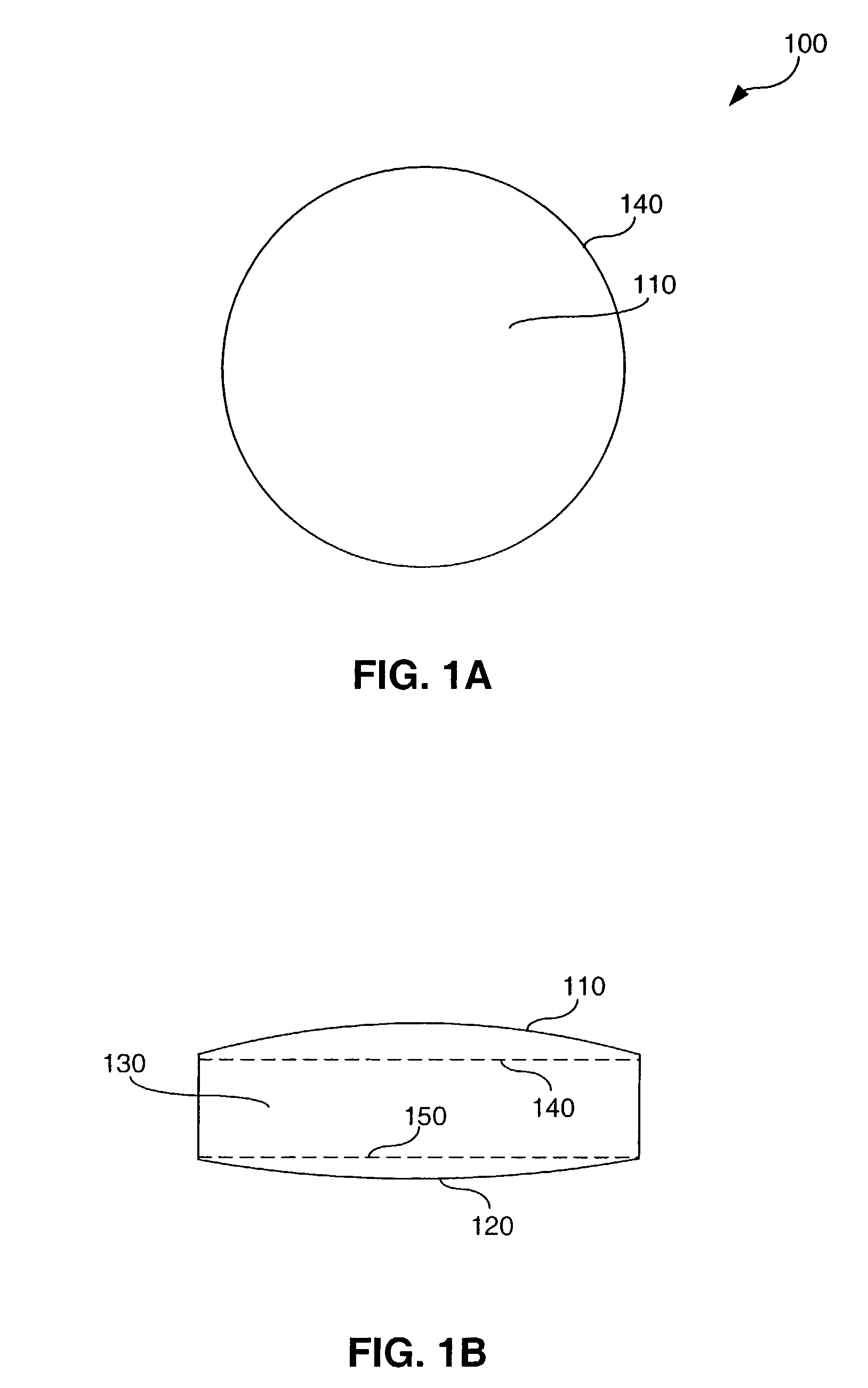
[0024]FIG. 1A illustrates optical element 100. Optical element 100 may be any type of optical element that permits light to pass through. As can be more readily seen in FIG. 1B, for the ease of illustration, optical element 100 has been selected to be a convex lens.

[0025]FIG. 1B illustrates a perspective view of optical element 100. Optical element 100 comprises front polished optical surface 110, rear polished optical surface 120, edge 130, front edge boundary 140 and rear edge boundary 150.

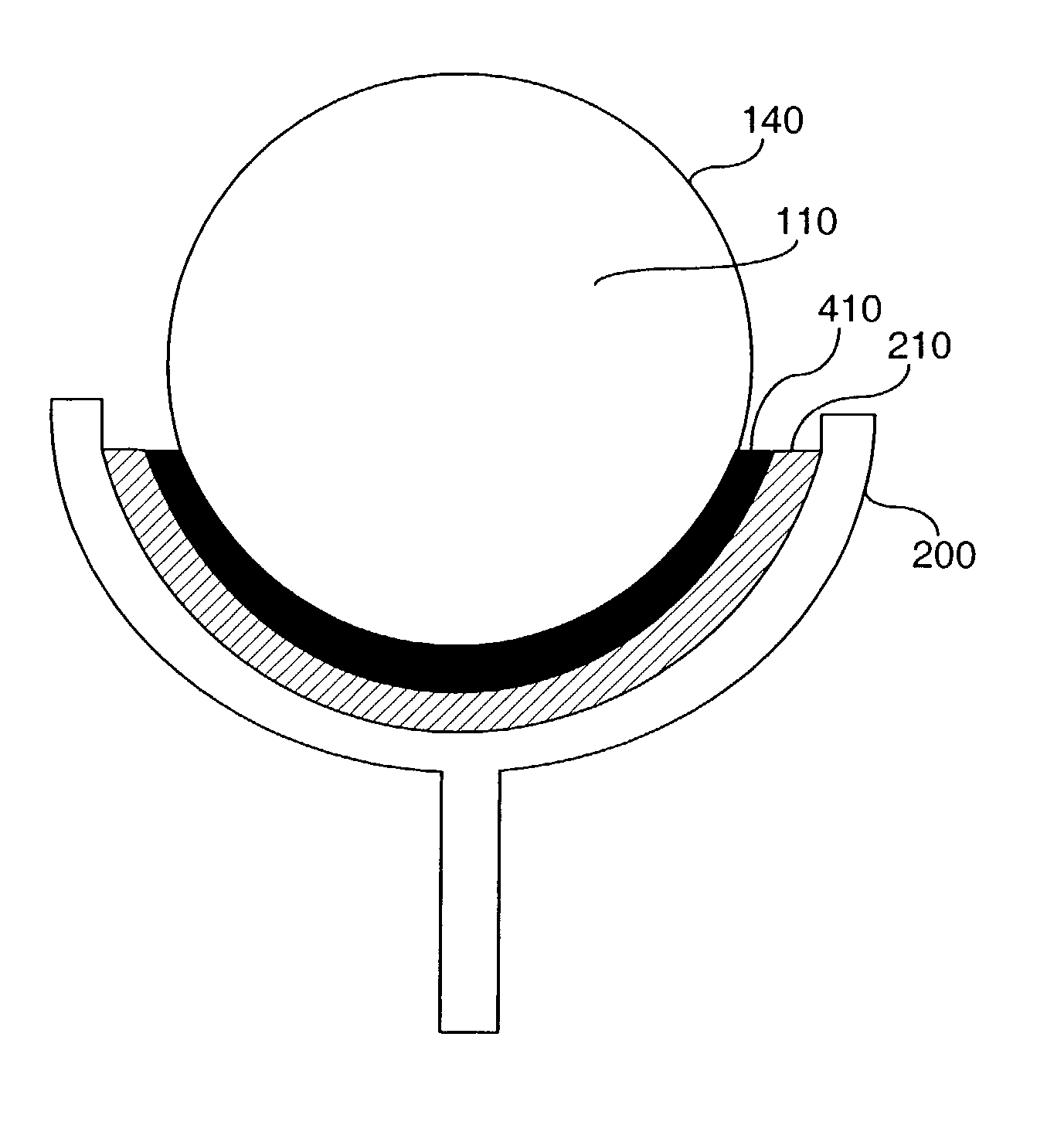
[0026]Front edge boundary 140 represents the points form...


PUM

PropertyMeasurementUnit
thicknessaaaaaaaaaa
thicknessaaaaaaaaaa
wavelengthsaaaaaaaaaa

Abstract

A method for reducing the scattered light emitted through an optical element is provided that protects adhesive used to hold the optical element in place from light induced deterioration. In one embodiment, the method includes applying a thin coating of an organoxy metallic compound to a region on an optical element where adhesive will be applied and exposing the organoxy metallic compound to ultra-violet light. Exposure to ultra-violet light converts the organoxy metallic compound to its corresponding metal oxide forming an optically inert, light absorbing coating that protects adhesive used to hold the optical element in place from light induced deterioration.

Description

BACKGROUND OF THE INVENTION[0001]1. Field of the Invention[0002]The present invention relates to securing optical elements, more particularly, to applying an optically inert, light absorbing coating on an optical element for the protection of adhesives used to secure optics from ultra-violet light.[0003]2. Related Art[0004]The secure positioning of optical elements within an optical system is crucial, particularly in very high precision optical systems, such as those used in photolithography. Optical system developers use several approaches to securely position optical elements within a system, including clamping an optical element in place, encasing an optical element entirely within an enclosure, and using an adhesive to hold an optical element in place. The current invention relates to approaches using an adhesive to hold an optical element in place. The term adhesive as used herein refers to any chemical compound used to secure an optical element, including but not limited to gl...

Claims


Application Information

Patent Timeline
Patent Type & Authority Patents(United States)
IPC IPC(8): B05D3/06B05D5/06G02B7/00C09J5/00B05D1/40C03C17/23C03C27/00G02B3/00G02B5/00G02B7/02
CPCG02B1/105G02B7/025G02B5/003Y10T156/10G03F7/70341G02B1/14C09J5/00B82B3/00
Inventor LIPSON, MATTHEWWILKLOW, RONALD A
Owner ASML HLDG NV
Why Eureka
Try Eureka