Band pass filter

a filter and band pass technology, applied in the field of band pass filter, can solve the problems of high steepness in the passing region, insufficient noise removal effect, and inability to obtain objective frequency characteristics

Inactive Publication Date: 2006-07-25
MITSUBISHI ELECTRIC CORP
View PDF3 Cites 28 Cited by
  • Summary
  • Abstract
  • Description
  • Claims
  • Application Information

AI Technical Summary

Benefits of technology

[0069]Therefore, according to the band pass filter of the invention, while the band width and the maximum gain are kept fixed, one of or both of the center frequency and the maximum gain can be made easily variable by a control signal from the outside in the state where the specific offset is given to the center frequency.

Problems solved by technology

However, since the filter characteristics of the second order band pass filter other than the maximum gain are theoretically determined by only the center frequency and the band width, there is a case where objective frequency characteristics can not be obtained.
For example, in the case where noise is mixed in the vicinity of the required frequency band, there has been a case where a noise removal effect can not be sufficiently obtained.
However, in the case of the single tuning system, also as shown in FIG. 10, in the case where the attenuation characteristic at a skirt part is desired to be enhanced, the steepness in a passing region becomes high, and it has been difficult to widen the band width.
On the contrary, in the case where the band width is desired to be widened, it has been difficult to enhance the attenuation characteristic at the skirt part.
Besides, in the fourth order band pass filter, when only the center frequency is changed by using a switched capacitor or the like and by changing a resistance value by a control signal from the outside, it is necessary to separately give control signals (fCLK) having different frequencies to the switched capacitors of the two second order band pass filters, and there has been a problem that a circuit scale becomes large.

Method used


Image

  • Band pass filter
  • Band pass filter
  • Band pass filter

Examples


embodiment 1

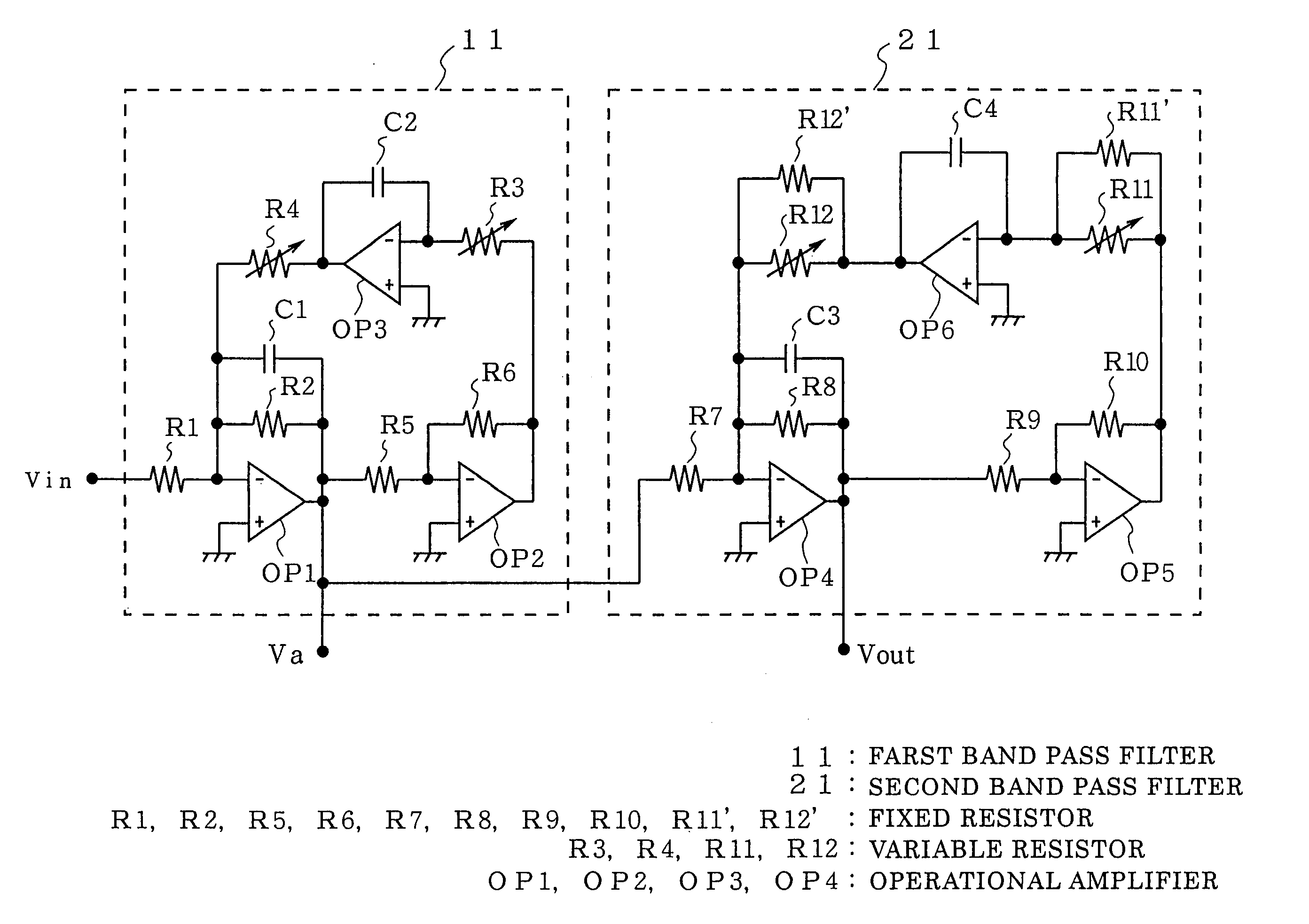
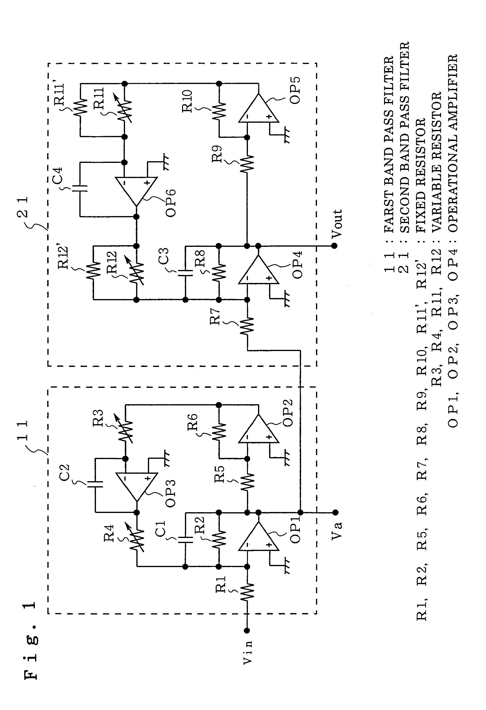
[0084]FIG. 1 is a view showing a circuit structure of a band pass filter according to embodiment 1.

[0085]The band pass filter shown in FIG. 1 is a fourth order band pass filter of a stagger tuning system obtained by series connecting a pair of second order band pass filters having different center frequencies and constructed of biquad circuits.

[0086]In the drawing, reference numeral 11 denotes a first stage second order band pass filter (first band pass filter), and its circuit structure is such that the resistor R3 and the resistor R4 in the biquad circuit shown in FIG. 7 are made variable resistors.

[0087]Reference numeral 21 denotes a second stage second order band pass filter (second band pass filter), and its circuit structure is such that each of the resistor R3 and the resistor R4 in the biquad circuit shown in FIG. 7 is replaced by a fixed resistor and a variable resistor connected in parallel to each other.

[0088]In the drawing, R1, R2, R5, R6, R7, R8, R9, R10, R11′ and R12′ ...

embodiment 2

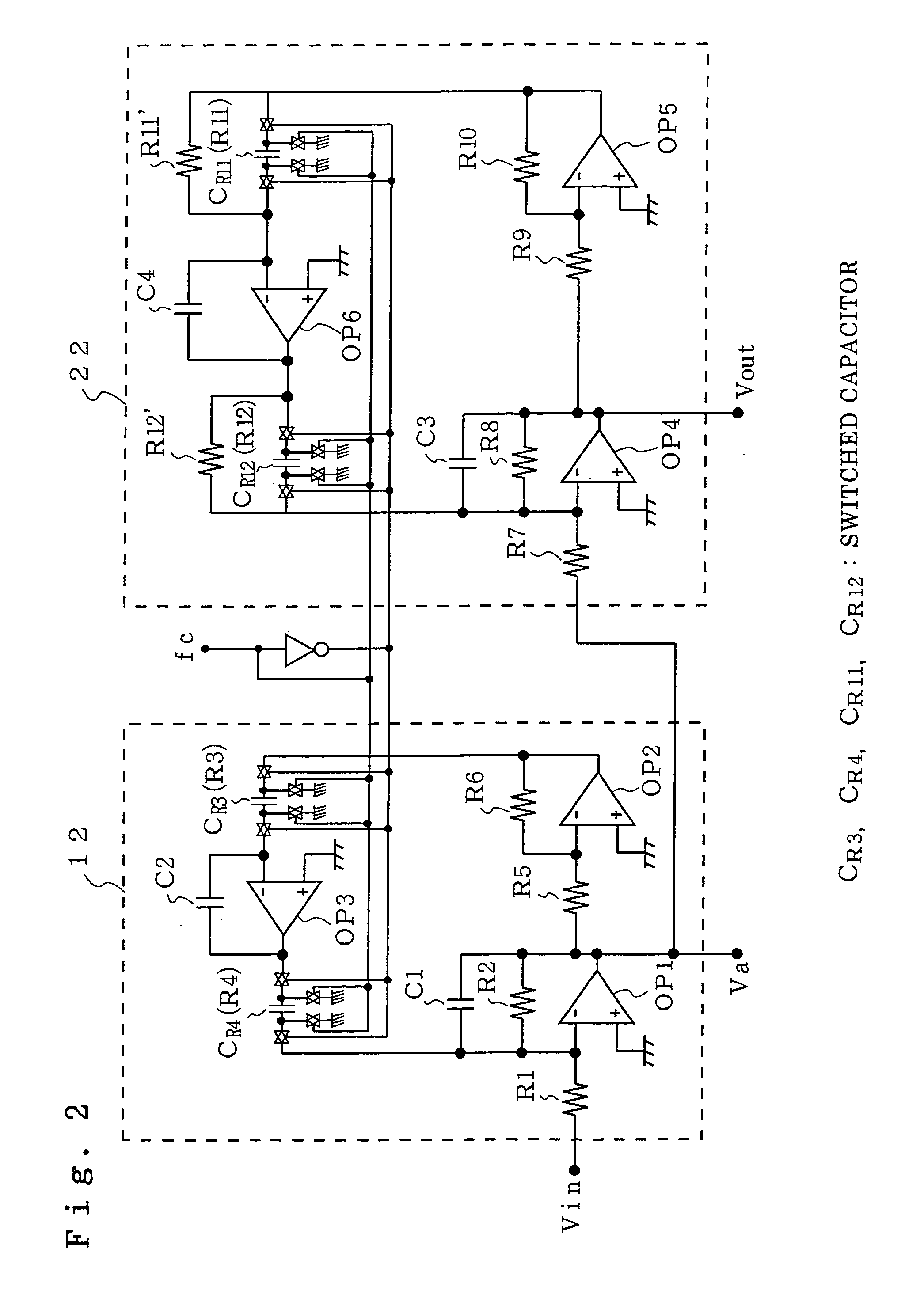
[0100]FIG. 2 is a view showing a circuit structure of a band pass filter according to embodiment 2.

[0101]The circuit structure of FIG. 2 is such that in FIG. 1 showing the circuit structure of the band pass filter according to embodiment 1, the variable resistors R3, R4, R11 and R12 are replaced by switched capacitors.

[0102]In the drawing, reference numeral 12 denotes a first stage second order band pass filter (first band pass filter), and 22 denotes a second stage second order band pass filter (second band pass filter).

[0103]Besides, CR3, CR4, CR11 and CR12 denote switched capacitors respectively corresponding to the variable resistor R3, the variable resistor R4, the variable resistor R11 and the variable resistor 12.

[0104]First, the respective characteristics (maximum gain (G01), band width (ωb1), and center frequency (ω01)) concerning the first stage second order band pass filter 12 as the first band pass filter (that is, the second order band pass filter whose input is Vin and...

embodiment 3

[0115]FIG. 3 is a view showing a circuit structure of a band pass filter according to embodiment 3.

[0116]In the circuit of the band pass filter according to embodiment 1 and shown in FIG. 1, the resistance values of R1 R7 are fixed, and the maximum gain is also fixed. On the other hand, in the circuit structure of the band pass filter according to this embodiment, as shown in FIG. 3, instead of the fixed resistors R1 and R7, variable resistors R21 and R22 are used to adjust the maximum gain.

[0117]In the drawing, reference numeral 13 denotes a first stage second order band pass filter (first band pass filter); 23, a second stage second order band pass filter (second band pass filter); R21, a variable resistor for adjusting the maximum gain of the first band pass filter 13; and R22, a variable resistor for adjusting the maximum gain of the second band pass filter 23.

[0118]First, the respective characteristics (maximum gain (G01), band width (ωb1), and center frequency (ω01)) concernin...


PUM


Abstract

A band pass filter includes a first band pass filter constructed of a biquad circuit and having a first center frequency, and a second bandpass filter constructed of a biquad circuit and having a second center frequency different from the first center frequency, and the first band pass filter and the second band pass filter are series connected, in which the first band pass filter and the second band pass filter have center frequency adjusting variable resistors varied at the same time, and a fixed resistor is connected in parallel to the center frequency adjusting variable resistor of one of the first band pass filter and the second band pass filter. As a result, the center frequency and / or the maximum gain can be made variable while the band width is fixed.

Description

BACKGROUND OF THE INVENTION[0001]1. Field of the Invention[0002]The present invention relates to a band pass filter which is a high order band pass filter obtained by series connecting plural secondary band pass filters having different center frequencies and can change its characteristics.[0003]2. Description of the Related Art[0004]Band pass filters used for various signal processing devices are often constructed of analog circuits, and most of them are used in such a state that characteristics (that is, maximum gain, band width, and center frequency) of the band pass filter are fixed.[0005]FIG. 5 is a view showing the characteristics of a general second order band pass filter.[0006]In the drawing, ω0 denotes a center frequency, G0 denotes a maximum gain, and ωb denotes a band width.[0007]Some band pass filters can vary their characteristics by using characteristic variable parts (that is, parts for making the characteristics of the band pass filter variable) such as variable resi...

Claims


Application Information

Patent Timeline
Patent Type & Authority Patents(United States)
IPC IPC(8): H03K5/00H03H9/00H03H11/04H03H11/12
CPCH03H11/1291H03H11/1252
Inventor HAGARI, HIDEKI
Owner MITSUBISHI ELECTRIC CORP
Why Eureka
Try Eureka