
Digital signal gating apparatus and method in a pulse receiver system

a pulse receiver and digital signal technology, applied in the field of data sorting, can solve the problems of easy deinterleaving of signals that would otherwise be quite confusing, one unacceptable pulse at the output, and the sorter was no longer locked in to the pulse train, and achieve the effect of accurate determination of the toa of the qualified pulse and high noise rejection threshold

Active Publication Date: 2006-07-25
NORTHROP GRUMMAN SYST CORP
View PDF10 Cites 22 Cited by
  • Summary
  • Abstract
  • Description
  • Claims
  • Application Information

AI Technical Summary

Benefits of technology

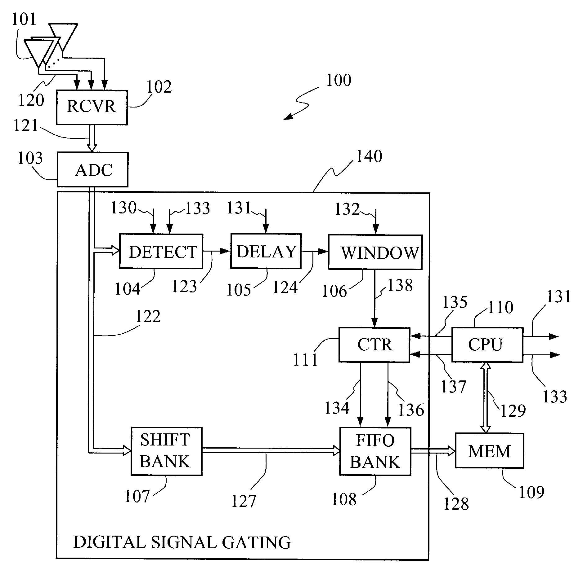
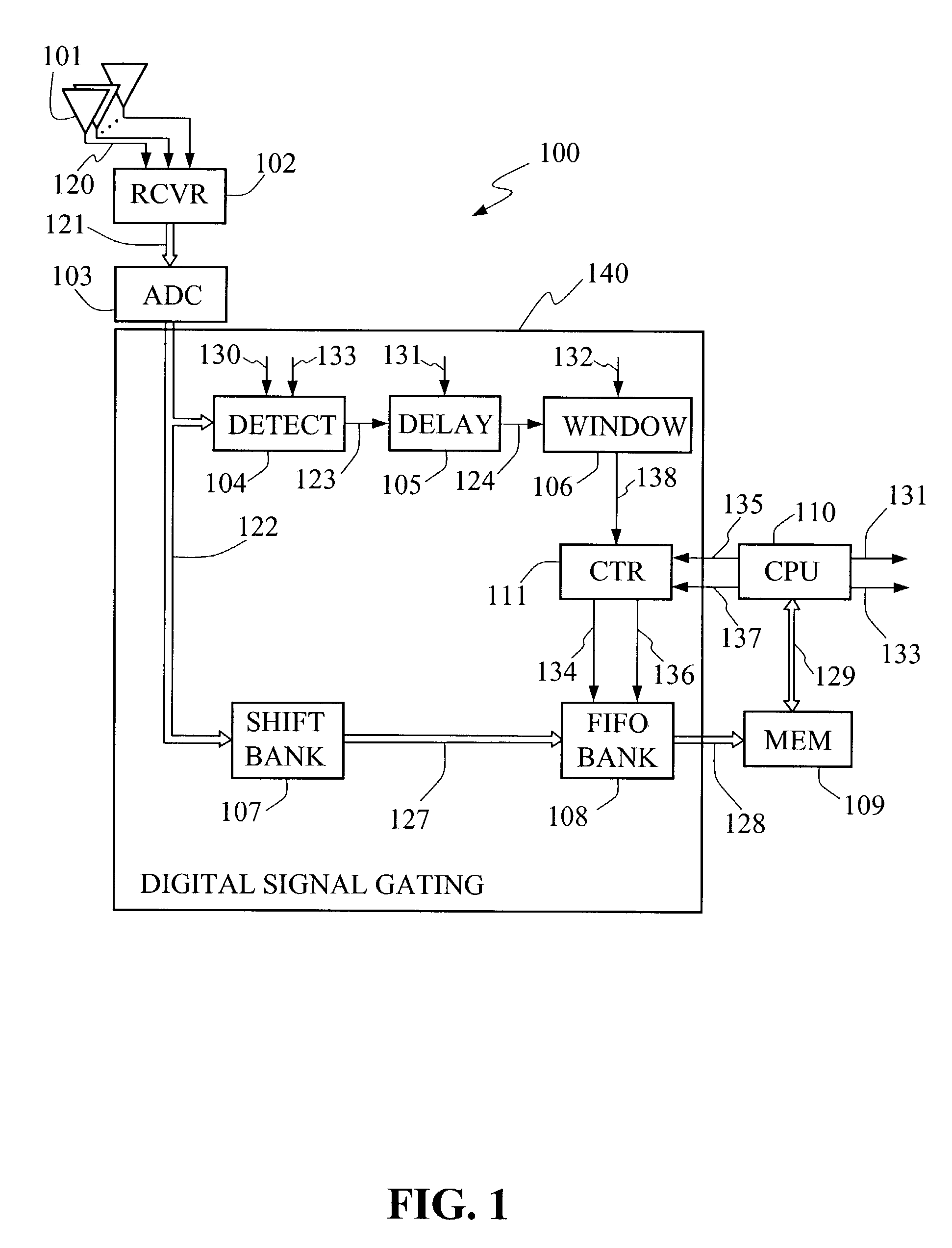
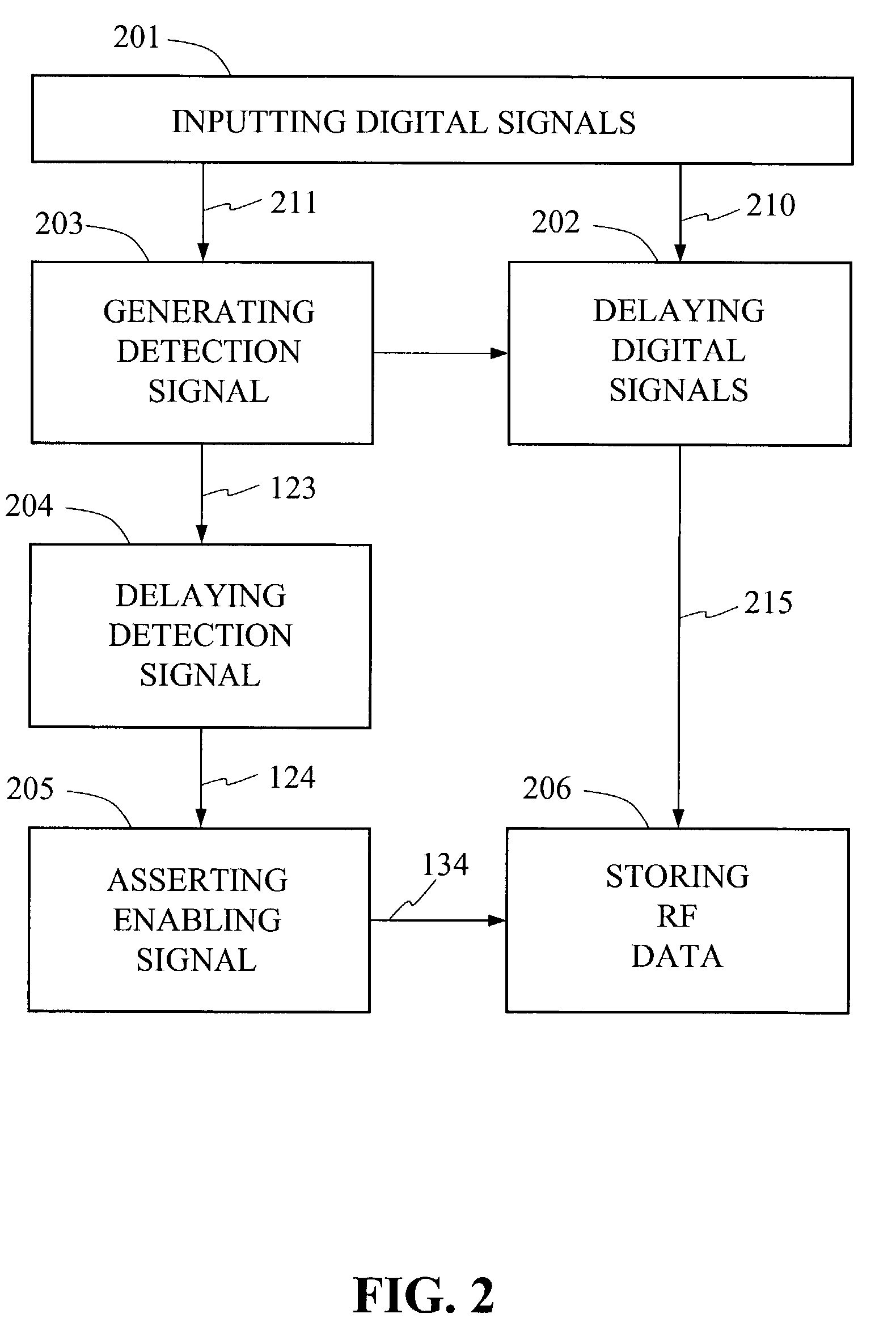
[0013]The digital signal gating apparatus embodiments of the present invention reside within the preprocessor of an RF pulse detection system After detecting an RF pulse, the digital signal gating apparatus selectively records RF pulse data from the received signals by generating a gating signal in the form of a data acquisition window that causes the complete record of the RF pulse to be extracted from a delayed version of the received signals. The present invention accomplishes this by using the gating signal to enable recording means to read into memory the digital signals after they have been delayed a predetermined amount of time. The several embodiments of the present invention permit the data corresponding to the entire RF pulse to be retained, avoiding the inadvertent loss of data preceding the point in time when the signal satisfies predetermined threshold and durational requirements.
[0014]The present invention provides a purposeful delay produced by a shift register that, in combination with a programmable durational requirement, allows for the use of a relatively high noise rejection threshold for pulse detection while retaining the entire sub-threshold portion of the leading edge of a pulse so that if the pulse qualifies as a valid pulse, based on duration above threshold for example, a more accurate determination of the TOA of the qualified pulse can be made.

Problems solved by technology

Failure to pass these tests can mean that the sorter was no longer locked on to the pulse train.
The decision to accept or reject the pulse is typically made after the pulse appears so that one unacceptable pulse may appear at the output before the sorter reacts.
Because pulse amplitude (PA) is a strong function of distance to the emitter, it can often easily deinterleave signals that would otherwise be quite confusing.

Method used


Image

  • Digital signal gating apparatus and method in a pulse receiver system
  • Digital signal gating apparatus and method in a pulse receiver system
  • Digital signal gating apparatus and method in a pulse receiver system

Examples


Embodiment Construction

[0020]An apparatus embodiment of the present invention receives digital signals generated by a receiver. The generated receiver digital signals including measures of the RF pulse amplitude, phase difference and instantaneous frequency collectively referred to as RF data. The received digital signals are bifurcated along two separate paths in the digital signal gating apparatus. Along the first path, each of the receiver output signals is conveyed to a first delaying means such as a shift register which continually and systematically delays the digital signals before reproducing the same signals at its output a fixed time later. The propagation time through first delaying means is represent by M system clock cycles. The output of the first delaying means, i.e., the delayed digital signals, are applied to memory means where the delayed digital signals are selectively stored in the manner described below.

[0021]Along the second path, the digital signals from the receiver, typically the ...


PUM


Abstract

A digital signal gating method and apparatus of a preprocessor in a detection system wherein the detection system includes a central processing unit, a main memory and a receiver, whereby the apparatus and method bifurcate received digital signals, delays them along a first path while subjecting the digital signals along a second path to detection, delay, and thresholding and thereby generates a gating signal from the second path so that digital signals of the first path, including pre-threshold amplitudes, may be recorded.

Description

CROSS REFERENCE TO RELATED APPLICATIONS[0001]This application claims priority from the following U.S. provisional Patent Application, the disclosure of which, including all appendices and all attached documents, is incorporated by reference in its entirety for all purposes: U.S. Provisional Patent Application Ser. No. 60 / 354,548, Richard Charles Pringle and Joanna S. Quan entitled, “DIGITAL SIGNAL GATING AND PULSE SORTING APPARATUS AND METHOD IN A PULSE RECEIVER SYSTEM,” filed Feb. 5, 2002. The present application also contains subject matter related to the subject matter disclosed in the following commonly-owned copending application that is being filed concurrently, and is hereby incorporated by reference in its entirety for all purposes: U.S. patent application Ser. No. 10 / 270,864, Richard Charles Pringle and Joanna S. Quan entitled, “PULSE SORTING APPARATUS FOR FREQUENCY HISTOGRAMMNG IN A RADAR RECEIVER SYSTEM.”FEDERALLY SPONSORED RESEARCH[0002]The invention was made with Govern...

Claims


Application Information

Patent Timeline
IPC IPC(8): H03K9/00
CPCG01S7/021
Inventor PRINGLE, RICHARD CHARLESQUAN, JOANNA S.
Owner NORTHROP GRUMMAN SYST CORP
Learn More