
Hydraulic machine, system for monitoring health of hydraulic machine, and method thereof

a technology for hydraulic machines and health monitoring, applied in the field of hydraulic machines, can solve the problems of large variation in the wear and tear of components, inability to accurately predict, and inability to prevent such damage, and achieve the effect of high reliability, predictive prevention of pump failures, and high reliability

Inactive Publication Date: 2006-08-01
KOMATSU LTD
View PDF8 Cites 48 Cited by
  • Summary
  • Abstract
  • Description
  • Claims
  • Application Information

AI Technical Summary

Benefits of technology

[0014]An object of the present invention is to be able to detect pump failure predictors in order to predictively prevent pump failure.
[0034]The system according to another aspect of the present invention is the hydraulic pump health monitoring system for a hydraulic machine, comprising a hydraulic pump, a drain filter which captures contaminants included in operating oil which flows to a drain of the hydraulic pump, and a differential pressure sensor which measures a filter differential pressure across the drain filter, comprising: a data collector which collects time series data of the filter differential pressure from the differential pressure sensor; a correlative relationship determining unit which determines a correlative relationship between the lapse time over a specified long period of time and the filter differential pressure based on the time series data of the filter differential pressure collected by the data collector; and a judging unit which determines a degree of deviation between the long-term correlative relationship determined by the correlative relationship determining unit and the filter differential pressure data over a specified recent short period of time, and estimate the lifespan or judge the existence of hydraulic pump abnormalities based on the determined degree of deviation. With this system, pump failure predictors can be detected beforehand or the timing that the pump will fail can be predicted, with a high level of reliability.

Problems solved by technology

However, there is a large variation in the wear of components even though the history of the life reducing factors is identical.
Therefore, methods based on the history of life reducing factors may be able to adjust the total time period, but cannot accurately predict the occurrence of pump failure and cannot predictively prevent such damage.
As a result, the reliability of the abnormality detection will be poor, so positive predictive notification of pump damage and functions which can predictively prevent this damage cannot be anticipated.
However, periodically stopping operation of the hydraulic machine and performing a failure diagnosis is a major burden for the supervisor of a hydraulic machine, and is not desirable.
Furthermore, hydraulic machines for work such as construction equipment like hydraulic shovels are machines which are primarily used for work at mines or construction sites, so stopping operation means stopping the mining or construction work, and causes serious economic impact.
However, with hydraulic pumps, the oil viscosity changes with oil temperature, so abnormalities cannot easily be detected accurately from differential pressure only.

Method used


Image

  • Hydraulic machine, system for monitoring health of hydraulic machine, and method thereof
  • Hydraulic machine, system for monitoring health of hydraulic machine, and method thereof
  • Hydraulic machine, system for monitoring health of hydraulic machine, and method thereof

Examples


Embodiment Construction

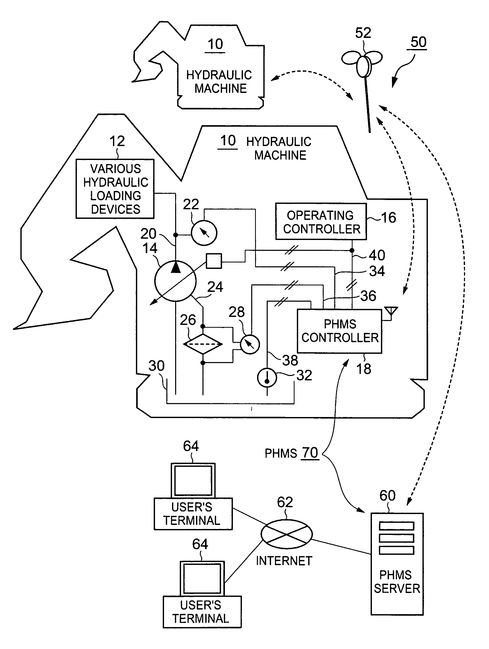
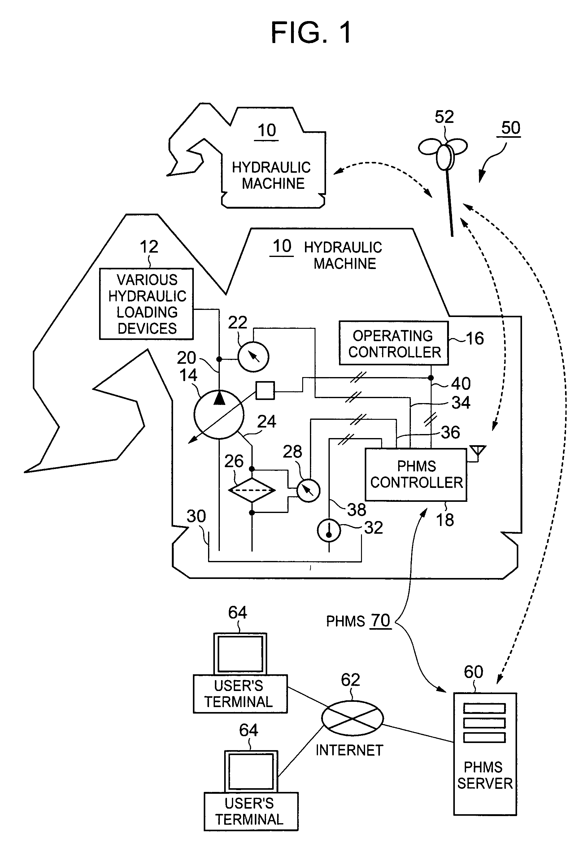
[0041]FIG. 1 shows the overall structure of an embodiment of the hydraulic machine and hydraulic pump health monitoring system of the present invention.

[0042]As shown in FIG. 1, a hydraulic machine 10 such as construction equipment has various hydraulic loading devices 12 (such as actuators like hydraulic motors and cylinders) which operate by hydraulic pressure, a hydraulic pump 14 for supplying pressurized operating oil to these hydraulic loading devices 12, and an operating controller 16 which issues commands for operating and controlling these hydraulic loading devices 12 and hydraulic pump 14. The hydraulic pump 14 may be either a fixed capacity type or a variable capacity type. However, in this embodiment the hydraulic pump is a swash plate pump which is a type of variable capacity pump. Capacity instructions 40 controlling the capacity of the hydraulic pump to a desired target value are given to the hydraulic pump 14 from the operating controller 16 as an instruction for oper...


PUM

PropertyMeasurementUnit
thresholdaaaaaaaaaa
differential pressureaaaaaaaaaa
pressureaaaaaaaaaa

Abstract

In a hydraulic machine, hydraulic pump failure is detected and the pump lifespan is estimated before the pump failure occurs. The discharge pressure 122, oil temperature 126, and drain filter differential pressure 120 are measured, a correlative relationship 128 between the filter differential pressure and the discharge pressure is determined, and a representative filter differential pressure 130 is calculated from this correlative relationship. Using an oil temperature-differential pressure correlation function, the representative differential pressure value 130 is corrected so that the variable component 132 caused by the oil temperature 126 is eliminated therefrom. The long-term trend and the short-term trend of the increase over time of the corrected differential pressure is calculated. A pump failure is predicted or the pump lifespan is estimated based on the degree of deviation between the long-term trend and the short-term trend.

Description

CROSS-REFERENCE TO RELATED APPLICATIONS[0001]This application relates to and claims priority from Japanese Patent Application No. 2004-152047, filed on May 21, 2004, the entire disclosure of which is incorporated herein by reference.BACKGROUND OF THE INVENTION[0002]1. Field of the Invention[0003]The present invention generally relates to a hydraulic machine, and more particularly relates to a hydraulic pump health monitoring system and method thereof for a hydraulic machine.[0004]2. Description of the Related Art[0005]Abnormality detection devices for liquid pumps such as hydraulic pumps have been made known in Japanese Patent Application Laid-open No. S59-194215, Japanese Patent Application Laid-open No. H7-280688, Japanese Patent Application Laid-open No. 2000-241306, and Japanese Patent Application Laid-open No. H8-114183 for instance.[0006]The hydraulic system failure detection device disclosed in Japanese Patent Application Laid-open No. S59-194215 detects factors (such as oil ...

Claims


Application Information

Patent Timeline
Patent Type & Authority Patents(United States)
IPC IPC(8): G01M3/00E02F9/24E02F9/20E02F9/22F04B49/10F04B51/00F15B19/00F15B20/00F15B21/041F15B21/08F16D31/02G01L13/00G01M3/26G01M13/00G01M99/00
CPCE02F9/20E02F9/226E02F9/2296F16D31/02F15B19/005F15B21/041F15B21/085F04B51/00
Inventor KAGEYAMA, MASATOSHOJI, YUKIOYOSHIDA, NOBUMI
Owner KOMATSU LTD
Learn More