System and method for controlling engine valve lift and valve opening percentage

a technology of internal combustion engine and valve opening percentage, which is applied in the direction of valve details, valve arrangement, valve drive, etc., can solve the problems of not allowing for any articulation, and achieve the effects of simple, robust and economical, effective, efficient and economical

Inactive Publication Date: 2006-08-01
FOLINO FRANK A
View PDF51 Cites 9 Cited by
  • Summary
  • Abstract
  • Description
  • Claims
  • Application Information

AI Technical Summary

Benefits of technology

[0017]These and other objects are well met by the infinitely variable valve timing and lifting systems of the present invention for uses with, for example, an internal combustion engine. In one aspect of the present invention presents an apparatus for essentially infinitely varying the valve lift. A cam configuration promotes phase angle control while, at the same time, providing the linear reciprocating motion to operate the valve opening and closing. The cam includes a fixed cam groove configuration that does not allow for any articulation to index the cam for changing the phase angle. It merely provides a reciprocating motion to exercise the valve and vary the lift. The cam configuration of the present invention not only incorporates the reciprocating motion for varying valve lift, but with a unique camshaft design and mechanical control module the cam is capable of articulating not only lead and lag phase angles for valve timing. The cam can also be designed to change the profile of the intake and exhaust motion characteristics.
[0019]It is significantly advantageous to be able to adjust the opening and closing phase angles of the intake and exhaust valves of an IC engine and accordingly change their timing in accordance with engine speed. By effective selection of these phase angles, it is possible to adjust the overlap of intake valves opening and exhaust valve closing as a function of engine speed and enhance engine performance. There has been a long felt need in the industry to achieve an effective, efficient and economical variable timing system. The present invention is a variable lift system with integrated variable timing mechanism that is effectively integrated into the variable lift mechanism and has produced a total system of infinitely variable valve timing and lift that is simple, robust and economical.

Problems solved by technology

The cam includes a fixed cam groove configuration that does not allow for any articulation to index the cam for changing the phase angle.

Method used


Image

  • System and method for controlling engine valve lift and valve opening percentage
  • System and method for controlling engine valve lift and valve opening percentage
  • System and method for controlling engine valve lift and valve opening percentage

Examples


Embodiment Construction

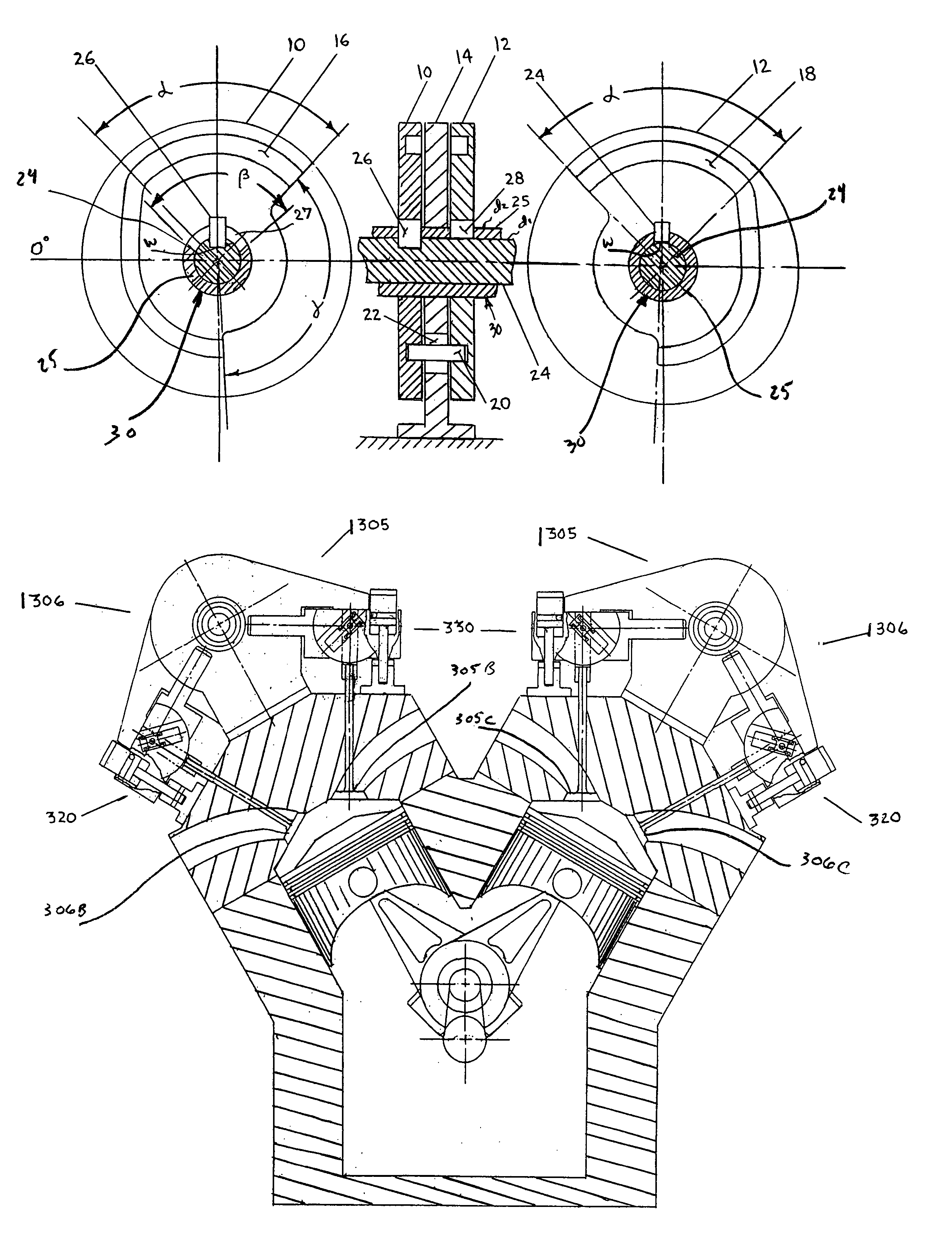
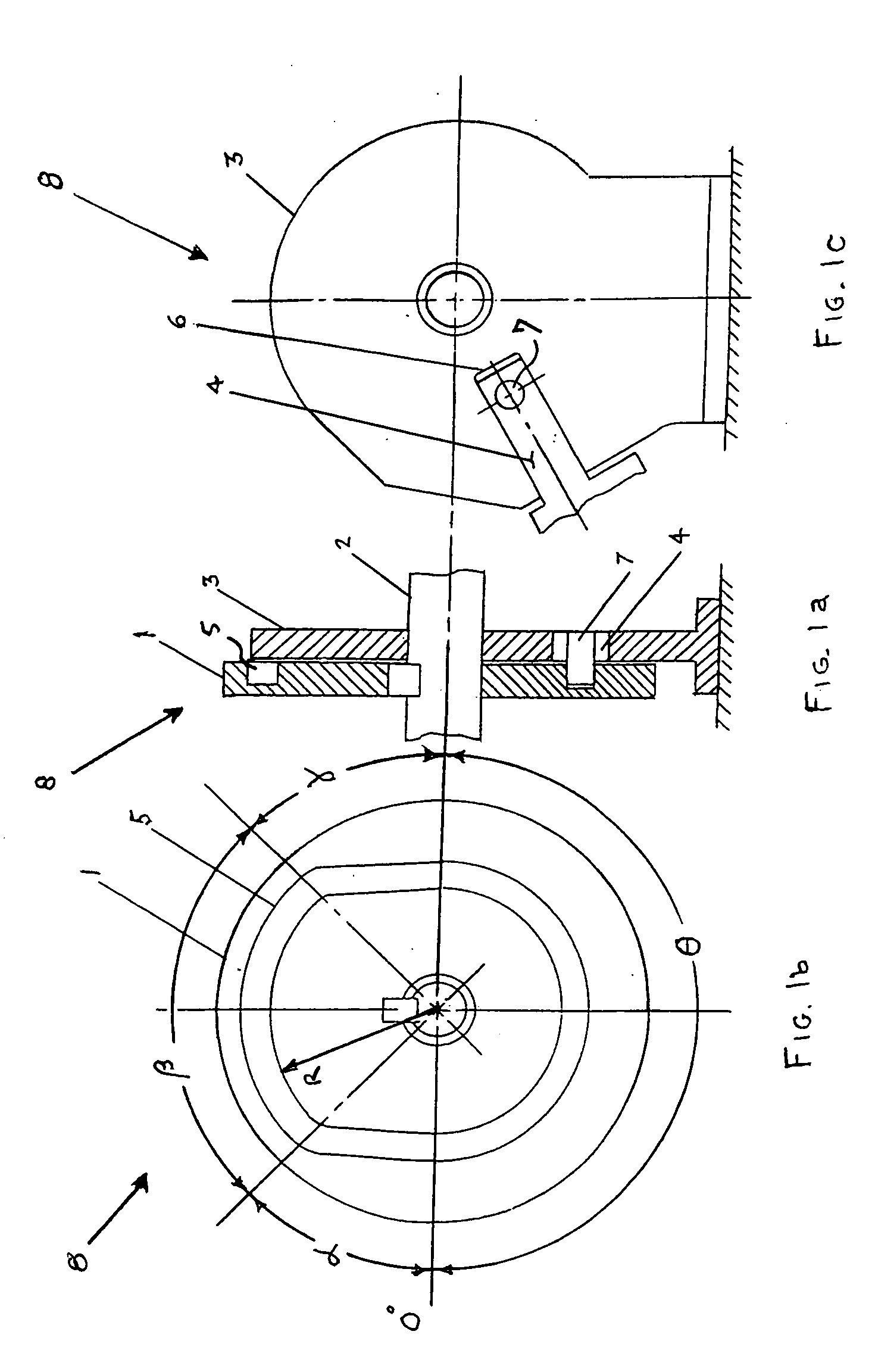
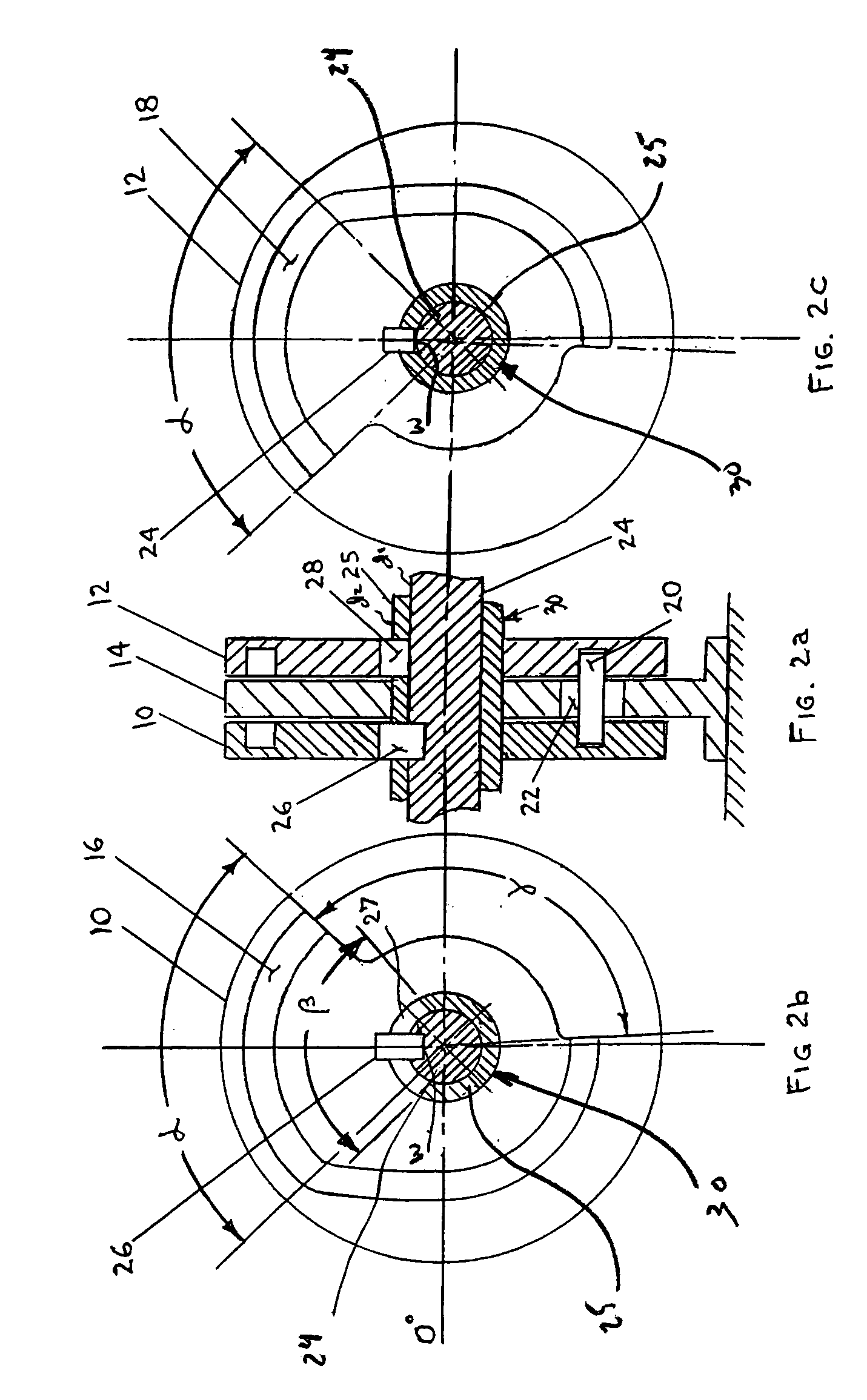
[0041]Shown in FIGS. 1A, 1B, 1C is a variable mechanism 8 that infinitely varies the valve lift to throttle the amount of air entering each cylinder of an engine as a function of engine speed. As shown, variable mechanism 8 illustrates only the motivating action of the system that has a mechanism that provides the variable valve lift (discussed in detail below).

[0042]Variable mechanism 8 illustrates rotating disc 1 keyed (FIG. 1B) to camshaft 2 and rotates relative to fixed stator housing 3 (FIG. 1C) in which slide 4 reciprocates in slot 6. Slide 4 reciprocation is affected by fixed cam 5 (FIGS. 1A, 1B) in rotating disc 1 and is reacted by cam follower 7 of slide 4. For example, at 0° start (FIG. 1A) follower 7 advances, indexes, or rotates through angle α and displaces slide 4 in slot 6 to its maximum out position. At this time, if the variable mechanism 8 is controlled to achieve maximum valve lift, the valve will be opened at its maximum opened condition through the cam angle β a...


PUM


Abstract

System and method for controlling internal combustion engine valve lift and valve opening by an arrangement of cams with overlapping cams track that synchronize and vary the rise, fall, and dwell of the inlet and exhaust valves of an IC engine.

Description

CROSS REFERENCE TO RELATED APPLICATIONS[0001]The present application is a continuation-in-part application of U.S. patent application Ser. No. 10 / 663,965, filed Sep. 16, 2003 and entitled “THERMAL COMPENSATING DESMODROMIC VALVE ACTUATION SYSTEM” (now U.S. Pat. No. 6,953,014), which is a continuation-in-part application of U.S. patent application Ser. No. 10 / 099,117, filed Mar. 15, 2002 and entitled “DESMODROMIC VALVE ACTUATION SYSTEM” (now U.S. Pat. No. 6,619,250), which claims benefit of U.S. Provisional Application Ser. No. 60 / 276,889, entitled “VARIABLE VALVE SYSTEM” filed on Mar. 16, 2001, and the present application also claims benefit of U.S. Provisional Application Ser. No. 60 / 590,527, entitled “VARIABLE VALVE SYSTEM” filed on Jul. 23, 2004. The above-identified applications are incorporated herein by reference.FIELD OF THE INVENTION[0002]The present invention relates generally to a system and method for controlling internal combustion (IC) engine valve lift and valve opening...

Claims


Application Information

Patent Timeline
Patent Type & Authority Patents(United States)
IPC IPC(8): F01L1/34
CPCF01L1/026F01L1/042F01L1/30F01L13/0015F01L1/352F01L2001/0537F01L13/0005
Inventor FOLINO, FRANK A.
Owner FOLINO FRANK A
Why Eureka
Try Eureka