Device for damping the needle lift in fuel injectors

a technology of fuel injector and needle lift, which is applied in the direction of fuel injection apparatus, fuel injection with sensors, charge feed systems, etc., can solve the problems of leakage via this throttle restriction flow, and achieve the effect of improving the minimum quantity capacity of fuel injector and reducing technical manufacturing complexity

Inactive Publication Date: 2006-08-01
ROBERT BOSCH GMBH
View PDF2 Cites 19 Cited by
  • Summary
  • Abstract
  • Description
  • Claims
  • Application Information

AI Technical Summary

Benefits of technology

[0012]With the design proposed according to the invention, it is possible to eliminate the use of a precision component as mentioned above, for example a needle stroke damper piston, by executing the function of the needle stroke damping by means of a flow through the nozzle needle spring chamber. On the one hand, the proposed design permits a significant reduction in the technical manufacturing complexity and on the other hand, it significantly improves the minimum quantity capacity of the fuel injector by reducing the needle opening speed. A separate precision component in the form of a needle stroke damper piston is not required. Instead, the nozzle spring chamber of the nozzle needle is filled from the high-pressure side via an inlet throttle or is pressure-relieved to the low-pressure side or to the working chamber via an outlet throttle.
[0013]The needle opening speed can be adjusted by means of appropriately dimensioning the flow cross sections and the lengths of the throttle restrictions of the inlet and outlet throttles. The closing speed of the nozzle needle is essentially determined by the cross-sectional area of the outlet throttle. It is thus possible, in principal, to set the opening speed and closing speed of the nozzle needle independently of each other through the dimensioning of the inlet throttle and outlet throttle and thus on the one hand, to achieve a slow opening of the injection valve element, e.g. a nozzle needle, and on the other hand, to achieve a rapid closing of the injection valve element of the fuel injector. A rapid closing of the injection valve element of a fuel injector permits an improvement in the emission levels of an autoignition internal combustion engine. A rapid closing of the injection valve element assures that a precisely defined termination point of the injection can be maintained, thus preventing subsequent injection of fuel into the combustion chamber, which would no longer be transformed during the combustion and would be contained in the exhaust in the form of uncombusted fuel and have an extremely negative influence on the HC content of this exhaust.
[0014]The production of a rapid needle closing also offers the possibility of keeping the quantity characteristic curve flat in the ballistic operating state of the nozzle, i.e. during the movement between its stroke stops and / or the injection valve element seat, which considerably improves the fuel metering precision.

Problems solved by technology

As a result, a leakage via this throttle restriction flows only during the short opening phase of the injection valve element.

Method used


Image

  • Device for damping the needle lift in fuel injectors
  • Device for damping the needle lift in fuel injectors
  • Device for damping the needle lift in fuel injectors

Examples


Embodiment Construction

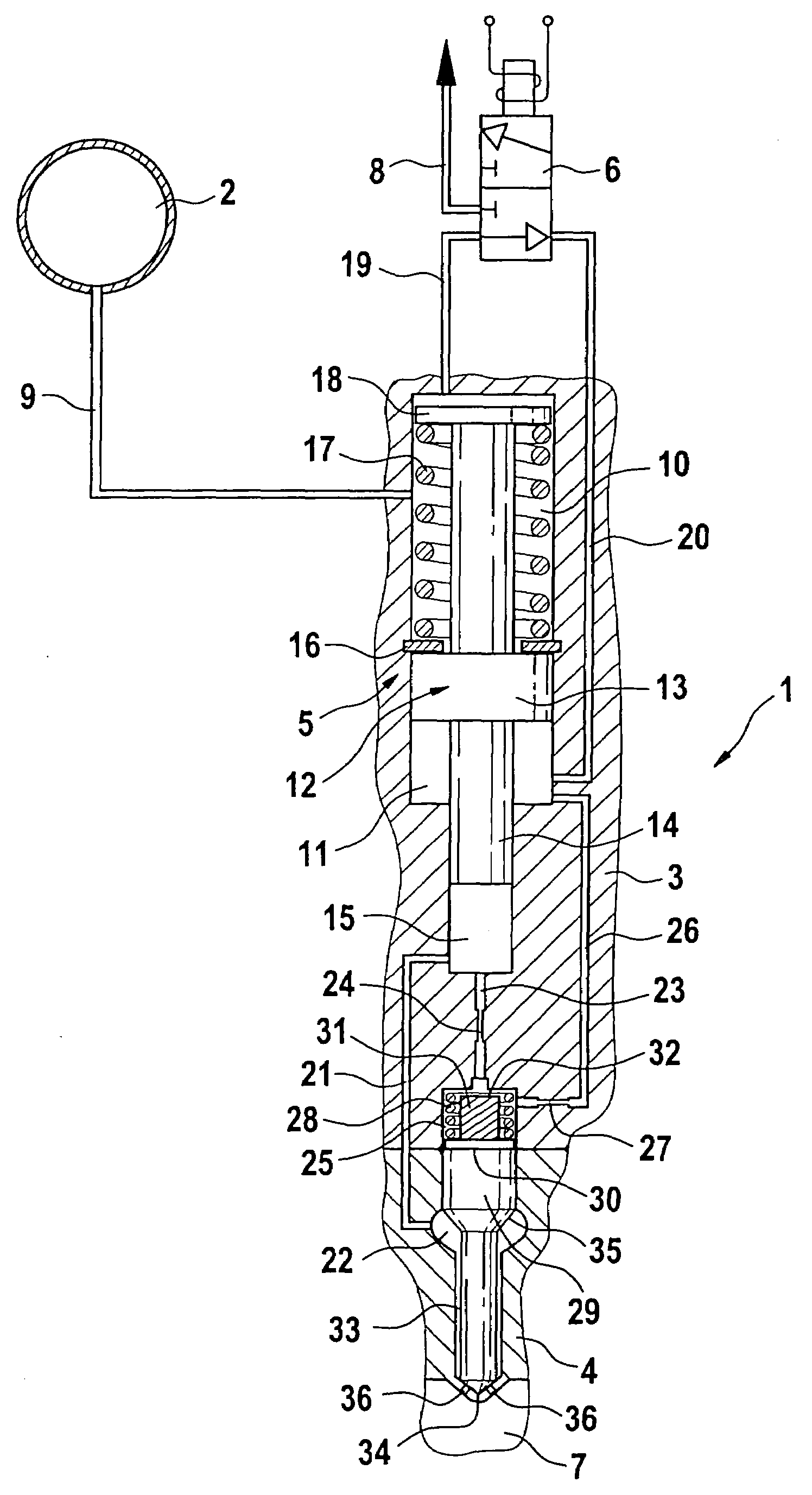
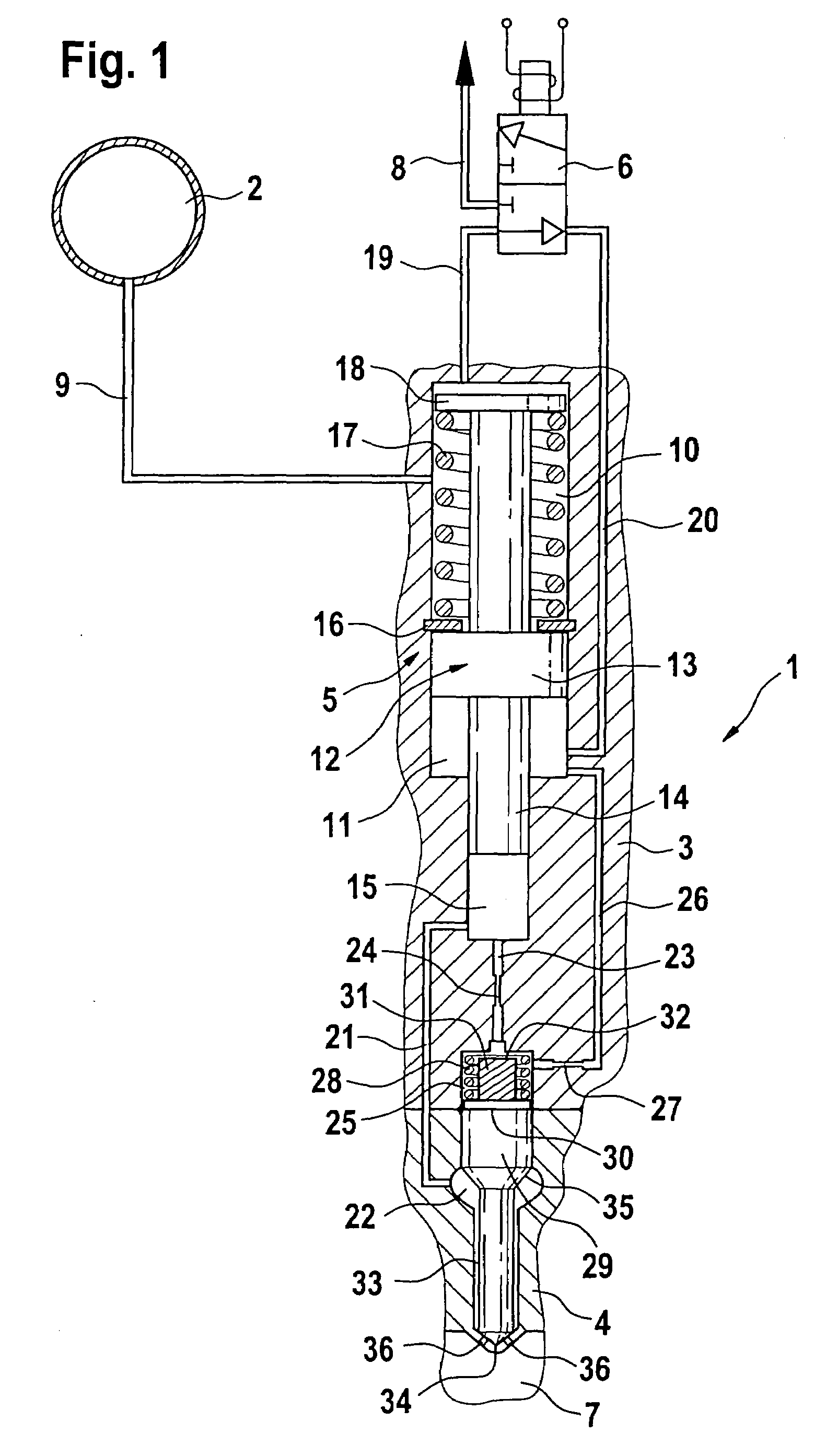
[0033]The fuel injection apparatus shown in FIG. 1 includes a fuel injector 1 that is supplied with highly pressurized fuel from a high-pressure accumulator 2. In addition to the high-pressure accumulator 2 and the fuel injector 1, the fuel injection apparatus includes a metering valve 6, which in the exemplary embodiment shown in FIG. 1 is embodied in the form of a 3 / 2-way valve. The fuel injector 1 includes an injector body 3 whose end oriented toward the combustion chamber is provided with a nozzle body 4. The tip 34 of the fuel injector 1, with the injection openings 36 provided there, protrudes into a combustion chamber 7, schematically depicted here, of an autoignition internal combustion engine.

[0034]The fuel injector shown in FIG. 1 includes a pressure booster 5 that has a working chamber 10 and a control chamber 11. A line 9 that extends from the high-pressure accumulator 2 to the injector body 3 of the fuel injector 1 acts on the working chamber 10 of the pressure booster ...


PUM


Abstract

A fuel injection apparatus for injecting fuel into the combustion chambers of an internal combustion engine. includes a high pressure accumulator, a pressure booster, and a metering valve. The pressure booster includes a working chamber and a control chamber that are separated from each other by an axially movable piston. A pressure change in the control chamber produces a pressure change in a compression chamber that acts on a nozzle chamber via a fuel inlet. The nozzle chamber encompasses a nozzle needle. A nozzle spring chamber that acts on the injection valve element can be filled on the high-pressure side via a line that leads from the compression chamber and contains an inlet throttle restriction. On the outlet side, the nozzle spring chamber is connected to a chamber of the pressure booster via a line that contains an outlet throttle restriction.

Description

CROSS-REFERENCE TO RELATED APPLICATIONS[0001]This application is a 35 USC 371 application of PCT / DE 03 / 01162 filed on Apr. 9, 2003.BACKGROUND OF THE INVENTION[0002]1. Field of the Invention[0003]It is possible to use both pressure-controlled and stroke-controlled injection systems to supply fuel to combustion chambers of autoignition internal combustion engines. In addition to unit fuel injectors, these fuel injection systems are also embodied in the form of unit pumps and accumulator injection systems. Accumulator injection systems (common rails) advantageously permit the injection pressure to be adapted to the load and engine speed. It is generally necessary to achieve the highest injection pressure possible in order to achieve high specific loads and reduce engine emissions.[0004]2. Prior Art[0005]The achievable pressure level in accumulator injection systems in use today is currently limited to approximately 1600 bar for strength reasons. In order to further increase pressure in...

Claims


Application Information

Patent Timeline
Patent Type & Authority Patents(United States)
IPC IPC(8): F02M47/02F02M45/00F02M61/10F02M47/00F02M55/02F02M57/02F02M59/10F02M61/16F02M61/20F02M63/00
CPCF02M57/025F02M59/105F02M61/205F02M2200/304F02M2200/24
Inventor KROPP, MARTINMAGEL, HANS-CHRISTOPHMACK, MANFREDGRIMMINGER, CHRISTIAN
Owner ROBERT BOSCH GMBH
Why Eureka
Try Eureka