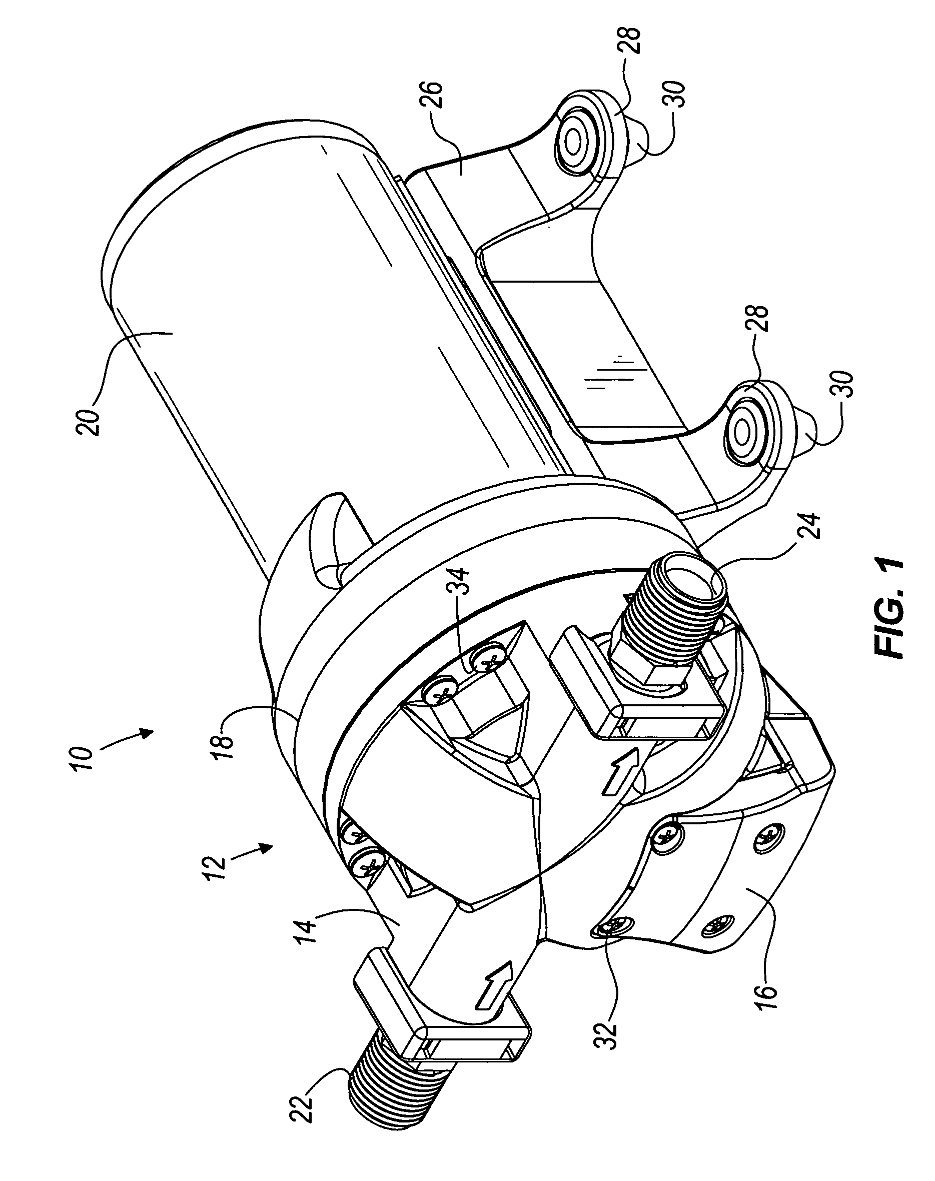
[0009]Some embodiments of the present invention provide a diaphragm for use with a pump having pistons driving the diaphragm to pump fluid through the pump. The pistons can be integrally formed in a body portion of the diaphragm, thereby resulting in fewer components for the manufacture and
assembly of the pump. Also, each of the pistons can be coupled (i.e., attached to or integral therewith) to the body portion of the diaphragm by a convolute. Each of the pistons can have a top surface
lying generally in a single plane. In some embodiments, each convolute is comprised of more material at its outer perimeter so that the bottom surface of each convolute lies at an angle with respect to the plane of the
piston top surfaces. The angled bottom surface of the convolutes allows the pistons a greater
range of motion with respect to the outer perimeter of the convolute, and can reduce diaphragm stresses for longer diaphragm life.
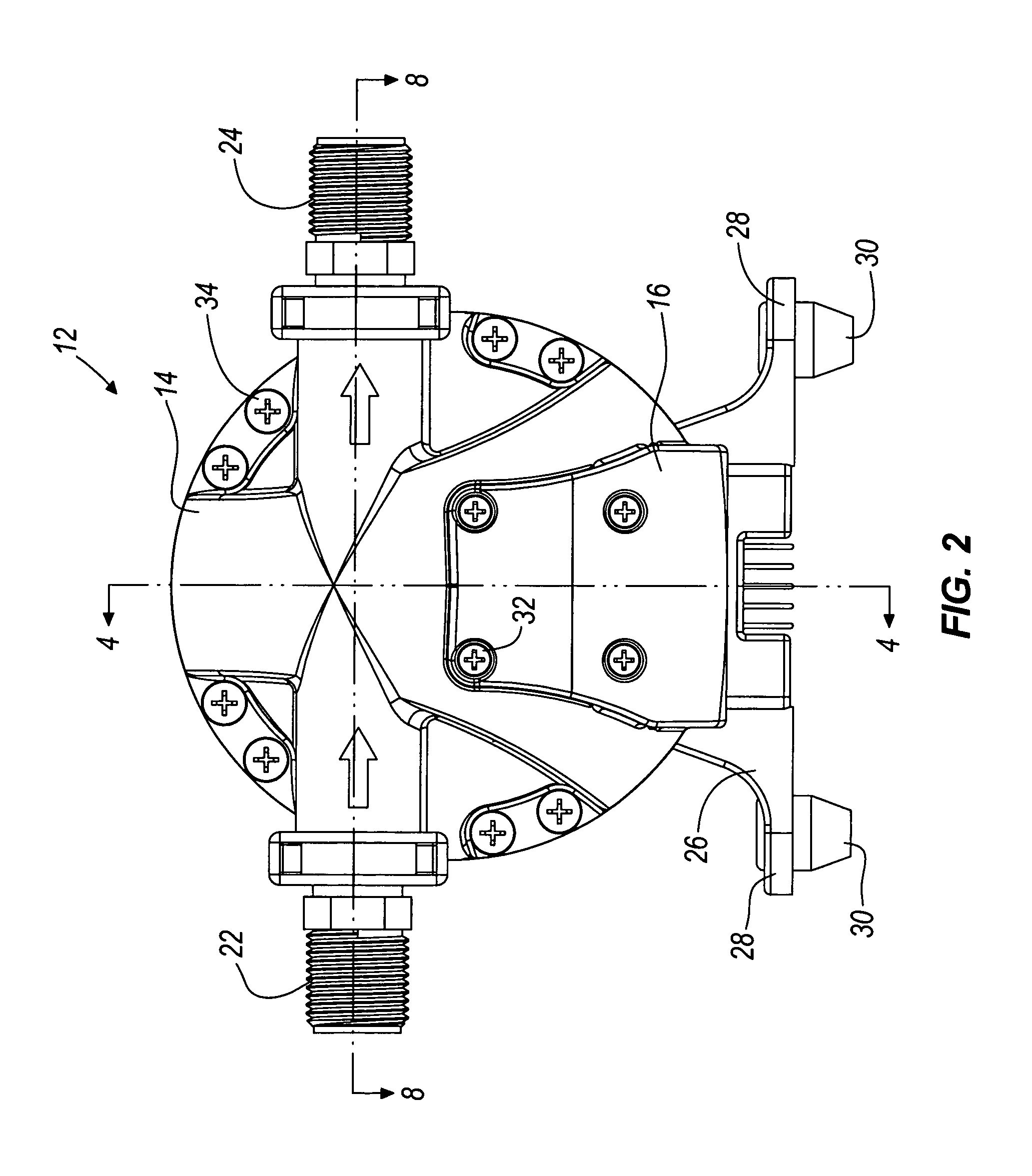
[0010]In some embodiments of the present invention, an outlet port of the pump is positioned tangentially with respect to the perimeter of an outlet chamber. The tangential outlet port allows fluid flowing in a circular path within the outlet chamber to continue along the circular path as the fluid exits the outlet chamber. This results in better pump efficiency, especially at lower pressures and higher flow rates.
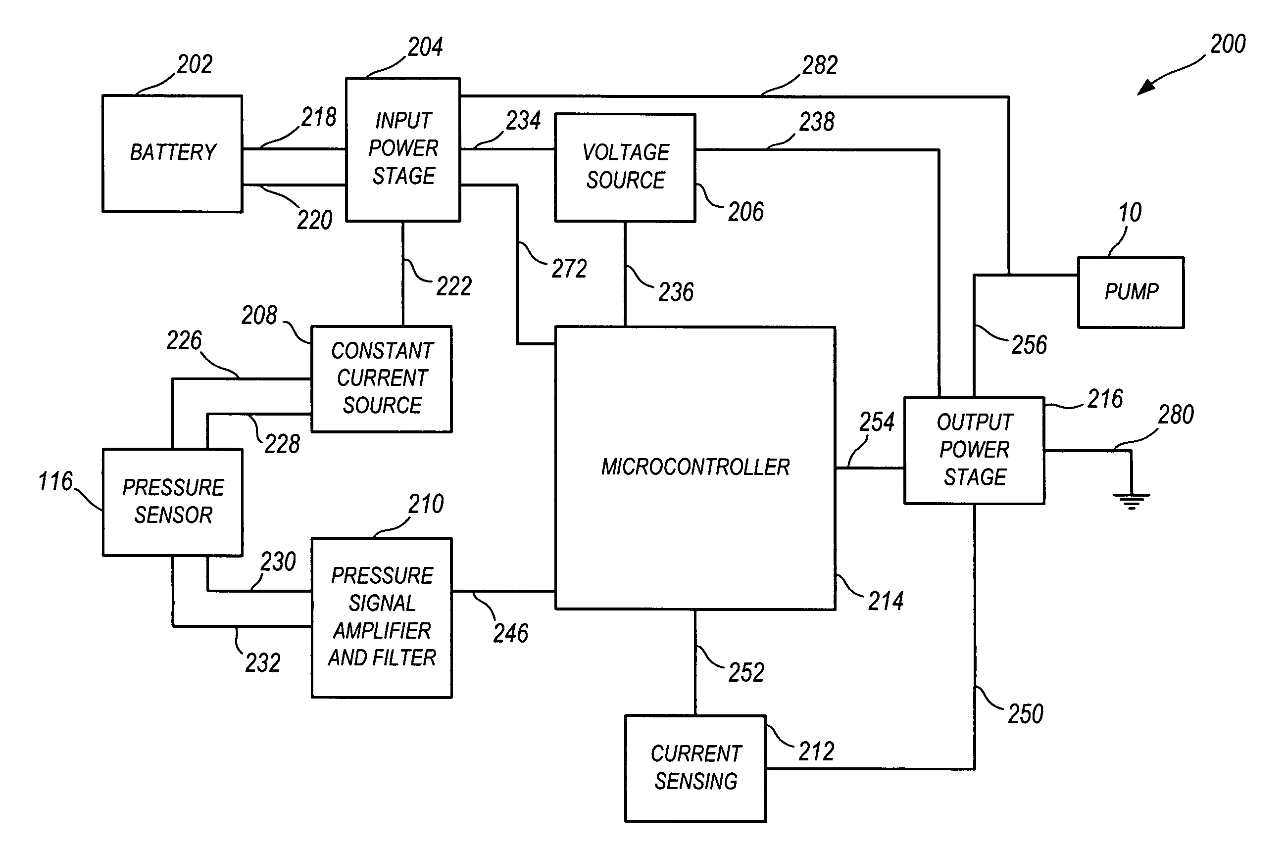
[0011]Some embodiments of the present invention further provide a pump having a non-
mechanical pressure sensor coupled to a pump control
system. However, some embodiments of the pump do not include a
pressure sensor or a pump control
system. The
pressure sensor provides a
signal representative of the changes in pressure within the pump to a
microcontroller within the pump control
system. Based upon the sensed pressure, the
microcontroller can provide a pulse-width modulation
control signal to an output power stage coupled to the pump. The output power stage selectively provides power to the pump based upon the control
signal. Due to the pulse-width modulation control
signal, the speed of the pump gradually increases or decreases rather than
cycling between completely “on” and completely “off,” resulting in more efficient and quieter operation of the pump.
[0012]The pump control system can also include an input power stage designed to be coupled to a battery. The microcontroller is coupled to the input power stage in order to sense the
voltage level of the battery. If the
battery voltage is above a high threshold (e.g., when the battery is being charged), the microcontroller can prevent power from being provided to the pump. If the
battery voltage is below a low threshold (e.g., when the
voltage available from the battery will only allow the pump to stall below the shut-off pressure), the microcontroller can also prevent power from being provided to the pump. In some embodiments, the
microprocessor only generates a control signal if the sensed
battery voltage is less than the high threshold and greater than the low threshold.
[0014]In some embodiments, the pump control system limits the current provided to the pump in order to prevent high currents from damaging the pump's components. The pump control system is capable of adjusting a current
limit value based upon the sensed pressure of the fluid within the pump. The pump control system can include a current-sensing circuit capable of sensing the current being provided to the pump. If the sensed current is less than the current
limit value, the microcontroller can generate a high control signal so that the output power stage provides power to the pump. If the sensed current is greater than the current
limit value, the microcontroller can generate a low control signal until the sensed current is less than the current limit value.
[0017]If the sensed pressure is less than the shut-off pressure value and the pump is turned off, the
microprocessor can generate a pulse-width modulation control signal to re-start the pump. The microcontroller can sense the pressure of the fluid within the pump and adjust the current limit value based on the sensed pressure. The microcontroller can also sense the current being provided to the pump. If the sensed current is greater than the current limit value, the microcontroller can adjust the pulse-width modulation control signal in order to provide less power to the pump. If the sensed current is less than the current limit value, the microcontroller can adjust the pulse-width modulation control signal in order to provide more power to the pump.

