Rotating fluid machine

a technology of rotating fluid machine and rotating valve, which is applied in the direction of machines/engines, liquid fuel engines, and combination engines. it can solve the problems of inability to secure sufficient sealing, pressure introduced into the bottom of the sealing holding groove, and leakage of pressure from the end of the sealing groove, so as to prevent leakage of pressure

Inactive Publication Date: 2006-08-01
HONDA MOTOR CO LTD
View PDF6 Cites 5 Cited by
  • Summary
  • Abstract
  • Description
  • Claims
  • Application Information

AI Technical Summary

Benefits of technology

[0009]Accordingly, an object of the present invention is to prevent leakage of pressure introduced into the bottom parts of seal holding grooves, thereby securing sealing performance of the vane seal.
[0011]In the configuration described above, as the pair of seal ancillary members fitted into engaging holes formed in the end faces of the vanes are provided with slits opening outward in the radial direction of the rotor and closing inward in the radial direction and the opposite ends of the vane seal are fitted into these slits. Therefore, the pressure of the gaseous phase working medium introduced into the bottom parts of the seal holding grooves can be restrained by the seal ancillary members from leaking out of the ends of the vane seal, and sealing performance can be secured by pressing with the pressure the vane seal against the inner circumferential face of the rotor chamber.
[0013]In the configuration described above, as the springy members accommodated in the bottom parts of the engaging holes in the vanes urges the seal ancillary members, the opposite ends of the vane seal can be tightly stuck into the slits in the seal ancillary members, and the pressure of the gaseous phase working medium introduced into the bottom parts of the seal holding grooves can be prevented more reliably from leaking out of the ends of the vane seal.

Problems solved by technology

However, as the vane seal formed in the U shape has a pair of ends, there is a fear that the pressure introduced into the bottom of the seal holding groove may leak from the ends of the vane seal, making it impossible to secure sufficient sealing merely with the centrifugal force and the urging force of the springs.

Method used


Image

  • Rotating fluid machine
  • Rotating fluid machine
  • Rotating fluid machine

Examples


Embodiment Construction

[0031]A preferred embodiment of the present invention will be described below with reference to the accompanying drawings.

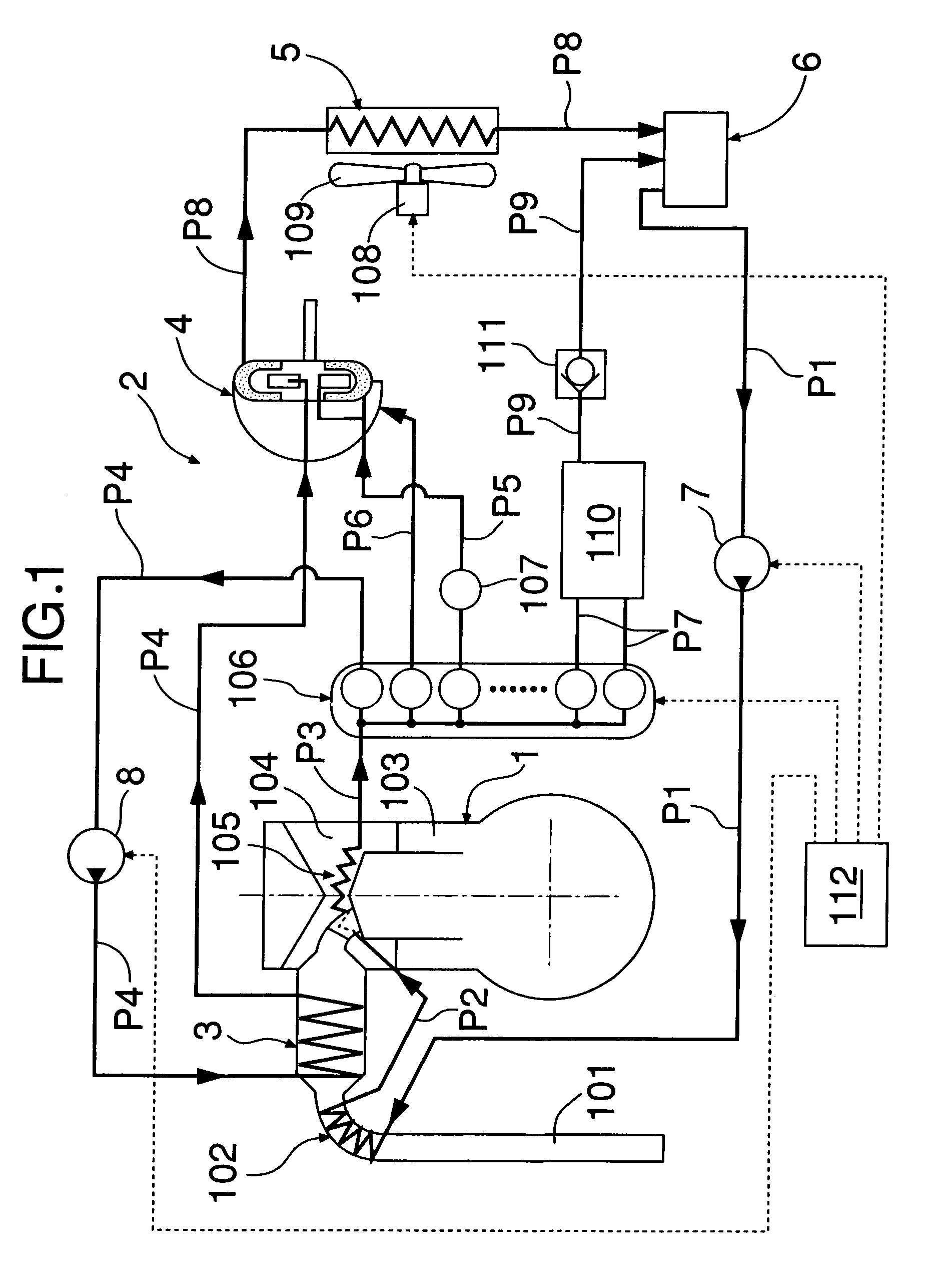
[0032]As shown in FIG. 1, a waste heat recovery device 2 for recovering the thermal energy of exhaust gas of an internal combustion engine 1 and outputting mechanical energy has an evaporator 3 for generating high temperature high pressure steam by heating water with heat derived from the exhaust gas of the internal combustion engine 1, an expander 4 for outputting axial torque with the expansion of the high temperature high pressure steam, a condenser 5 for cooling and liquefying reduced temperature reduced pressure steam discharged from that expander 4, a tank 6 for storing the water discharged from the condenser 5, and a low pressure pump 7 and a high pressure pump 8 for supplying water in the tank 6 to the evaporator 3 again.

[0033]The water in the tank 6 is pressurized to 2 to 3 MPa by the low pressure pump 7 arranged on a passage P1, and preheated as it pass...


PUM


Abstract

A rotating fluid machine is provided with a rotor chamber, a rotor accommodated in the rotor chamber, and vanes guided by vane grooves formed in the rotor. A U-shaped vane seal is held by a seal holding groove formed in the end face of each of the vanes. The opposite ends of the vane seal are fitted into slits in seal ancillary members which are fitted into engaging holes formed in the end faces of each of the vanes. The seal ancillary members are pressed by springs toward the inner circumferential face of the rotor chamber. The pressure of a gaseous phase working medium introduced into the bottom parts of the seal holding grooves is restrained from leaking out of the ends of the vane seal by the seal ancillary members. Thus, sealing performance can be secured by pressing the vane seal against the inner circumferential face of the rotor chamber.

Description

[0001]This Nonprovisional application claims priority under 35 U.S.C. § 119(a) on Patent Application No(s). 2002-370177 filed in JAPAN on Dec. 20, 2002, the entire contents of which are hereby incorporated by reference.BACKGROUND OF THE INVENTION[0002]1. Field of the Invention[0003]The present invention relates to a vane type rotating fluid machine which converts the pressure energy of a gaseous phase working medium into the rotational energy of a rotor and vice versa.[0004]2. Description of the Related Art[0005]Japanese Patent Laid-Open No. 2000-320543 discloses a rotating fluid machine provided with a vane-piston unit combining vanes and pistons, wherein pistons slidably fitted into cylinders provided in radial directions in a rotor converts the pressure energy of a gaseous phase working medium into the rotational energy of the rotor and vice versa via a power converting device composed of annular grooves and rollers, and vanes slidably supported by the rotor in radial directions ...

Claims


Application Information

Patent Timeline
Patent Type & Authority Patents(United States)
IPC IPC(8): F03C2/00F04C2/00F01K23/10F01B13/06F01B21/04F01C1/344F01C19/06F01C19/10F01C21/04F01C21/08F03C1/02F03C2/30
CPCF01C1/3446F01C21/0809F01C21/04F01C19/10
Inventor ICHIKAWA, HIROSHITAKAHASHI, TSUTOMUKIMURA, YASUNARIENDOH, TSUNEO
Owner HONDA MOTOR CO LTD
Why Eureka
Try Eureka