Particle distribution interposer and method of manufacture thereof

a technology of interposers and particle distribution, which is applied in the field of interposers, can solve the problems of bridging of electrical current between adjacent conductive members, and increasing the amount of mold flash, so as to improve the distribution of conductive particle particles, improve the conductivity and efficiency, and reduce the loss of elastomeric materials

Inactive Publication Date: 2006-08-01
IBM CORP
View PDF14 Cites 16 Cited by
  • Summary
  • Abstract
  • Description
  • Claims
  • Application Information

AI Technical Summary

Benefits of technology

[0012]It is an additional object and advantage of the present invention to provide a method for making interposer interconnect members with improved conductive particle distribution.
[0013]It is a further object and advantage of the present invention to provide a method of making interposers with less flashing or loss of elastomeric material.
[0014]Other objects and advantages of the present invention will in part be obvious, and in part appear hereinafter.
[0015]In accordance with the foregoing objects and advantages, the present invention provides a more effective interposer for use with an integrated chip package. The interposer of the present invention comprises a non-conductive carrier sheet with conductive interconnect members mounted therein and positioned in spaced relation to one another. The conductive interconnect members are formed from an elastomeric material having a mixture of spherical and non-spherical conductive particles suspended therein. Due to the fabrication method and structure, the non-spherical conductive particles of the present invention are positioned substantially perpendicularly to the contact face of the interconnect member, thereby resulting in higher conductivity and efficiency.
[0016]The mold of the present invention comprises a two piece mold with first and second sets of vias formed in the first and second mold sections, respectively, which permit the injected elastomer mixture to flow completely through the mold cavity. This flow pattern aligns the non-spherical conductive particles within the elastomer substantially perpendicular to, and extending partially through, the contact face of the newly formed interconnect member. The exit side of the two piece mold is further contacted by support posts of a separable mold interface that together define a network of vent passages. The vent passages created by the mold interface allow venting of the mold cavities and the exit flow of the elastomer mixture.
[0017]The method of the present invention facilitates fabrication of an interposer such that the conductive particles suspended in the elastomer solution are positioned substantially perpendicularly to the contact surfaces of the formed interconnect members. This perpendicular positioning results in an overall increase in conductivity due to the extension of the conductive particles through the end of the contact faces of the interconnect members. Furthermore, due to the improved flow pattern and venting through the second set of vias, there is less pressure within the mold during injection, resulting in less mold flash along the non-conductive carrier. Mold flash can result in bridging of electrical current between adjacent conductive members when the interposer is utilized.

Problems solved by technology

Mold flash can result in bridging of electrical current between adjacent conductive members when the interposer is utilized.
Use of smaller particles would otherwise increase the amount of bridging because they can more easily escape along the non-conductive carrier than larger particles, thus increasing the amount of mold flash.
The venting through the second set of vias alleviates this mold flash, however, and the use of smaller particles and polymer chains does not increase mold flash and bridging.

Method used


Image

  • Particle distribution interposer and method of manufacture thereof
  • Particle distribution interposer and method of manufacture thereof
  • Particle distribution interposer and method of manufacture thereof

Examples


Embodiment Construction

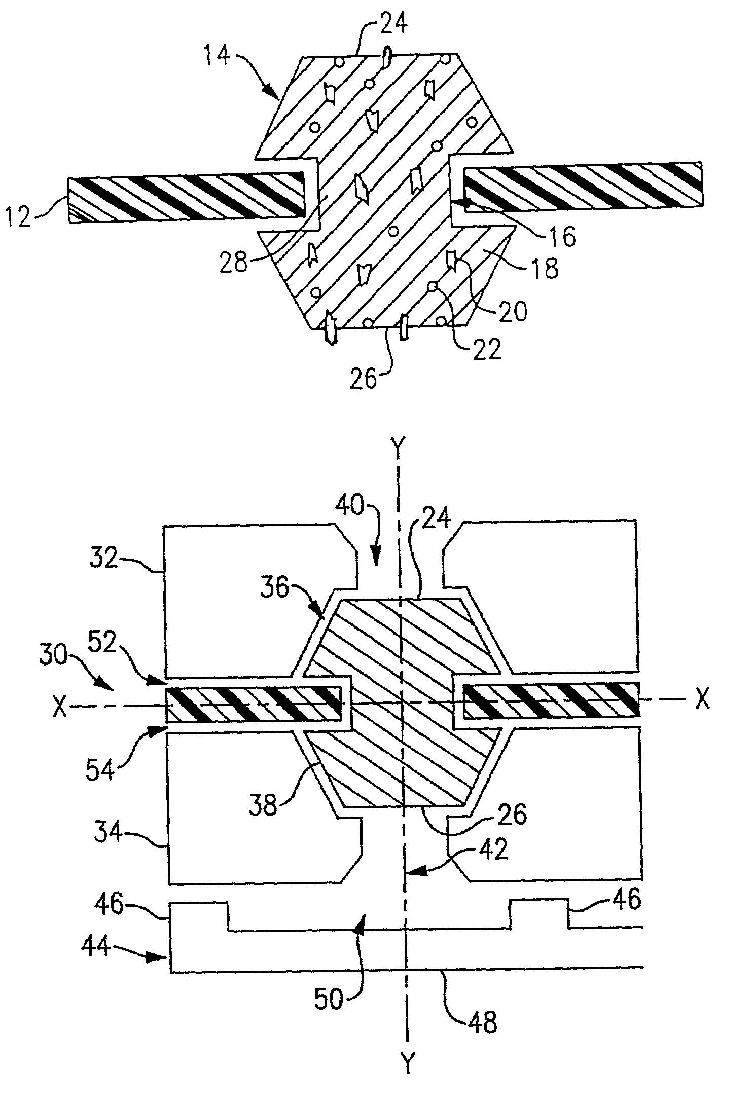
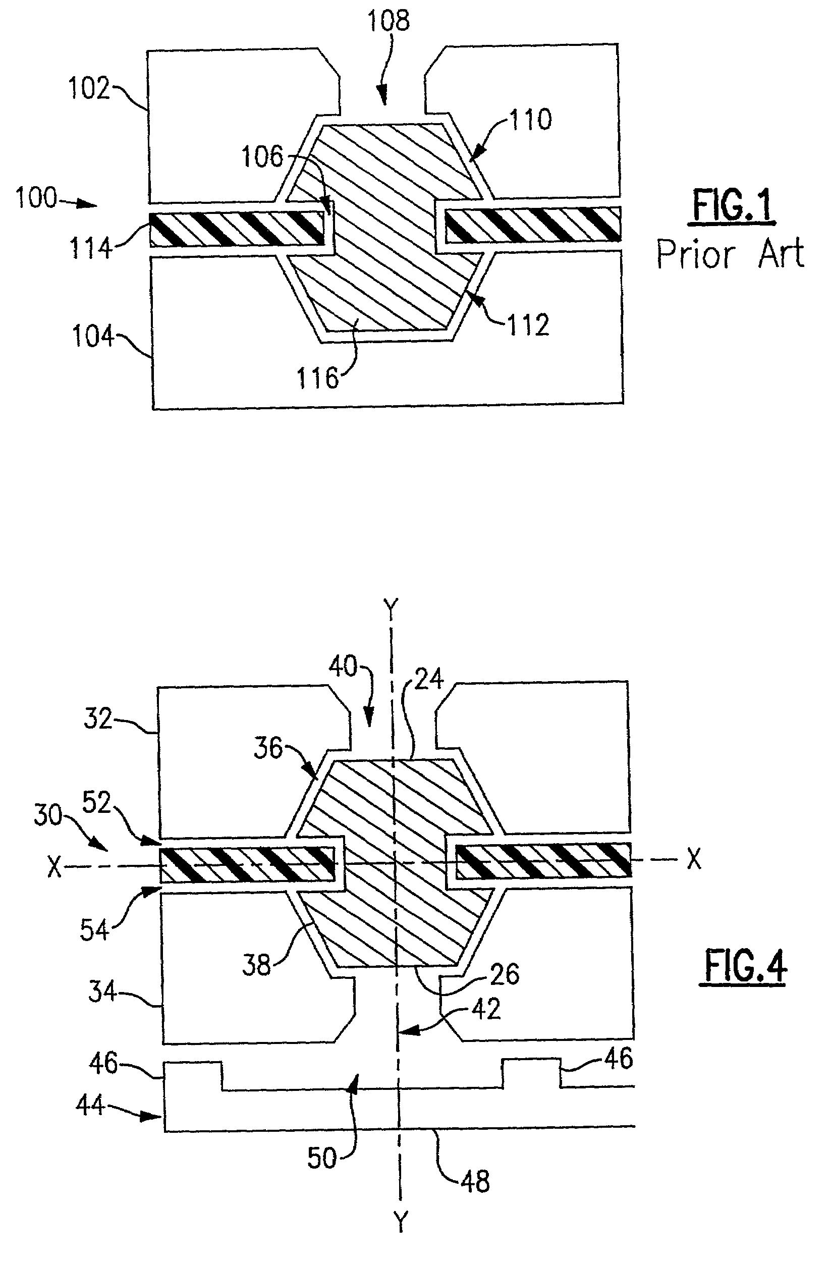
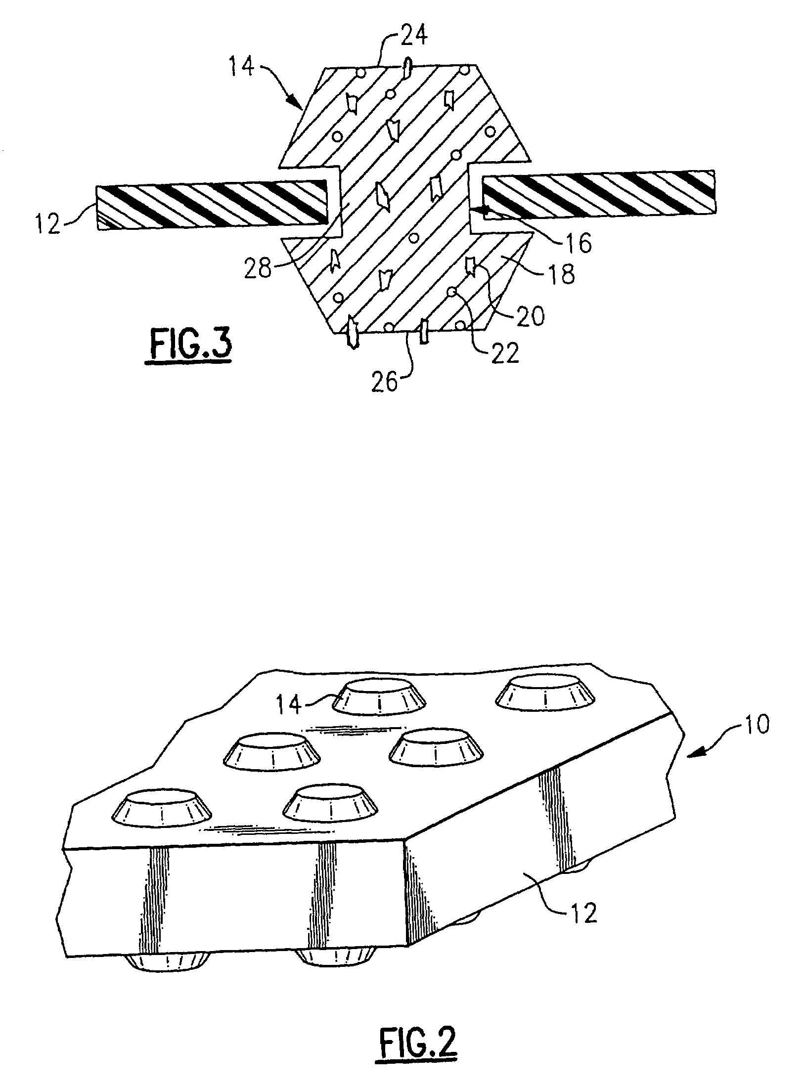
[0023]Referring now to the drawings wherein like reference numerals refer to like parts throughout, there is seen in FIG. 2 an interposer, designated generally by reference numeral 10, comprising a non-conductive carrier sheet 12 and conductive interconnect members 14. Non-conductive carrier sheet 12 is a conventional insulator material used in flexible circuits, e.g., a polyimide such as DuPont Kapton® or a polyester such as DuPont Mylar®, with an array of passages 16, as illustrated in FIG. 3, that extend completely though the sheet in a predetermined pattern. The passages 16 containing the conductive interconnect elements 14 can be arranged to correspond to the electrical contacts on a chip and a printed circuit board to which the chip, for instance, is to be attached.

[0024]Conductive interconnect member 14 comprises a substantially homogeneous elastomeric mixture of an elastomeric material 18 and a plurality of conductive particles 20, 22. Elastomeric material 18 can be composed...


PUM

PropertyMeasurementUnit
conductiveaaaaaaaaaa
pressureaaaaaaaaaa
elastomericaaaaaaaaaa

Abstract

An interposer comprising a non-conductive carrier sheet with a pre-arranged pattern of conductive interconnect members positioned therethrough and formed from an elastomeric thermoplastic with suspended spherical and non-spherical conductive particles. The non-spherical conductive particles of the present invention are positioned substantially perpendicularly to and partially through the contact faces of the interconnect member, thereby resulting in higher conductivity and efficiency. The interposer is formed by a mold comprising two sections with first and second sets of vias formed in the first and second mold sections, respectively, which permit the injected elastomer mixture to flow completely through the mold cavity and thereby aligns the non-spherical conductive particles. The exit side of the mold is further contacted by support posts of a separable mold interface creating a network of vent passages for venting of air and the elastomer mixture, resulting in less pressure within the mold and less mold flash.

Description

BACKGROUND OF THE INVENTION[0001]1. Field of Invention[0002]The present invention relates generally to interposers used in integrated semiconductor packages, and more particularly to a mold and method for fabricating interposers having improved structural and electrical integrity.[0003]2. Description of Prior Art[0004]Developments in integrated chip packages have substantially increased the amount of wiring required for input / output connections, while the sizes of the packages have decreased dramatically. Electrical leads for the I / O connections placed around the perimeter of the chip are restricted in number by the limited space around the ever shrinking chip. One method of handling the increase in number of I / O connections has been to replace the electrical leads with electrical contacts mounted on the surface of the chip instead of the contacts extending around the perimeter.[0005]Several problems arise when a chip with surface mounted electrical contacts is brought in direct con...

Claims


Application Information

Patent Timeline
Patent Type & Authority Patents(United States)
IPC IPC(8): H01R4/58B29C45/00B29C45/14H01L21/48H01L23/498H05K3/10H05K3/40
CPCB29C45/0013B29C45/14344H01L21/486H01L23/49827H01L23/49883H05K3/4069H05K3/101H01L2924/0002H05K2201/0314H05K2201/10378H05K2203/0113H01L2924/00
Inventor BRODSKY, WILLIAM L.
Owner IBM CORP
Why Eureka
Try Eureka