Windmill for wind power generation

a windmill and wind power technology, applied in the direction of wind turbines, renewable energy generation, greenhouse gas reduction, etc., can solve the problems of deteriorating aerodynamic properties of windmills, poor power generation efficiency, and inability to achieve rotational numbers more than the wind speed

Inactive Publication Date: 2006-08-01
TAISEI TECHNO
View PDF30 Cites 41 Cited by
  • Summary
  • Abstract
  • Description
  • Claims
  • Application Information

AI Technical Summary

Benefits of technology

[0008]Hence, it is object of the invention to provide a windmill for wind power generation having a high power generation efficiency by enabling one to rotate the windmill with an excellent power generation efficiency at a wind speed region of a wide range by improving a shape of a blade of a vertical shaft type windmill.
[0010]Further, the above-described object can effectively be achieved by making the Reynolds number fall in a range of 30,000 through 3,000,000.
[0011]Further, the above-described object can effectively be achieved by making the lift coefficient fall in a range of 1.0 through 1.4.
[0012]Further, the above-described object can further effectively be achieved by forming the notch portion from a position of 35% through 45% of a chord length from a front edge thereof over to a rear edge thereof.

Problems solved by technology

However, in the case of the former of the vertical shaft type (drag type), there poses a problem that when a peripheral speed ratio (blade end speed / wind speed becomes 1, a moment for rotating the windmill more than the peripheral speed ratio is not generated, even when the wind speed is increased, a rotational number more than the wind speed cannot be achieved and a power generation efficiency is poor.
However, when the peripheral speed is smaller than 1, the aerodynamic property of the windmill is deteriorated and the moment for rotating the windmill is reduced.
Further, there is a drawback that a starting moment is small and starting from a stationary state becomes very difficult.
However, the windmill is a windmill of a horizontal shaft type and there poses a problem that even when the power generation efficiency is increased, a number of parts is increased and the cost is increased.
Therefore, there is a drawback that the cost of the apparatus is increased in order to achieve the same power generation function.

Method used


Image

  • Windmill for wind power generation
  • Windmill for wind power generation
  • Windmill for wind power generation

Examples


Embodiment Construction

[0021]An embodiment of the invention will be explained with reference to the drawings as follows.

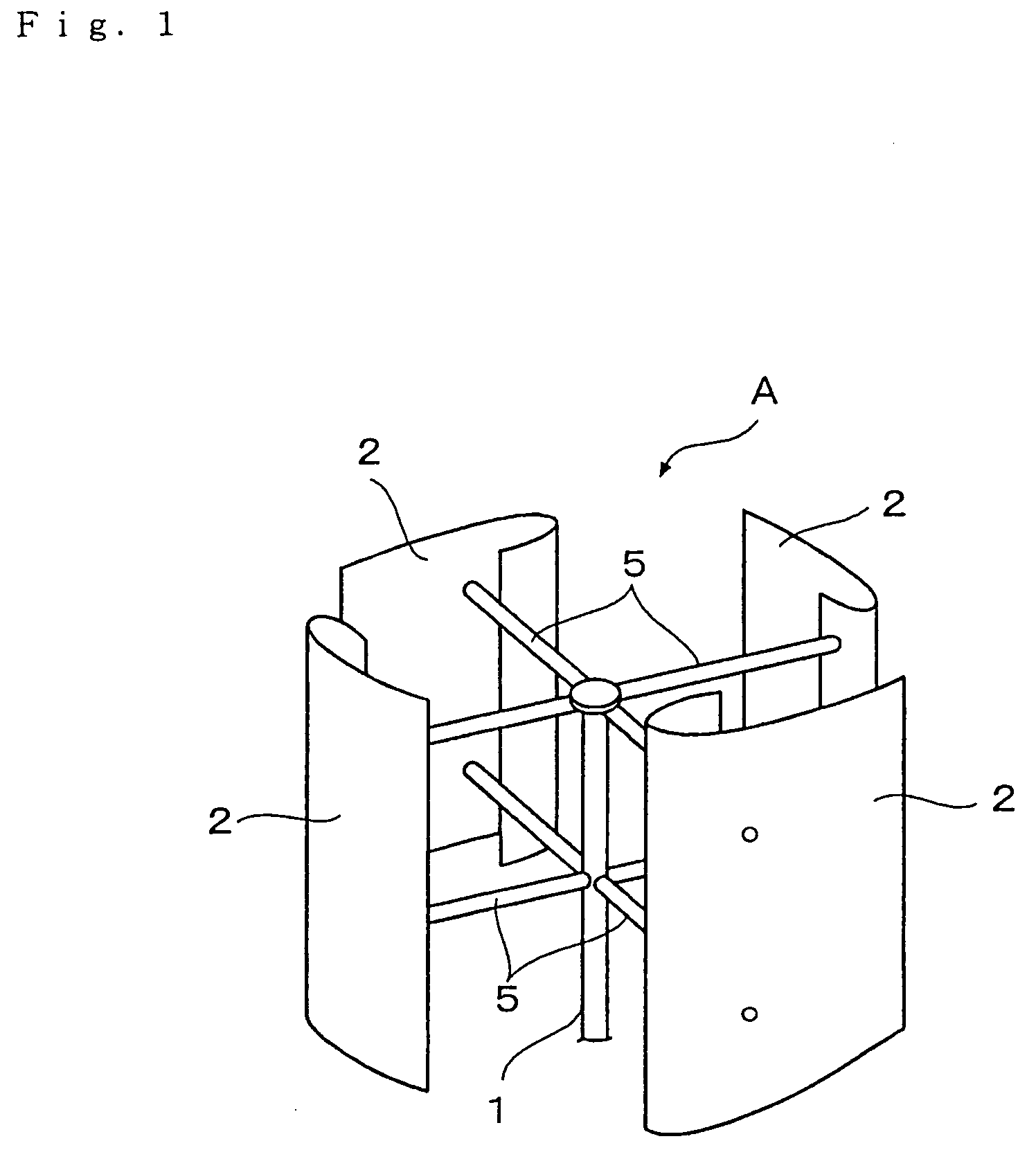
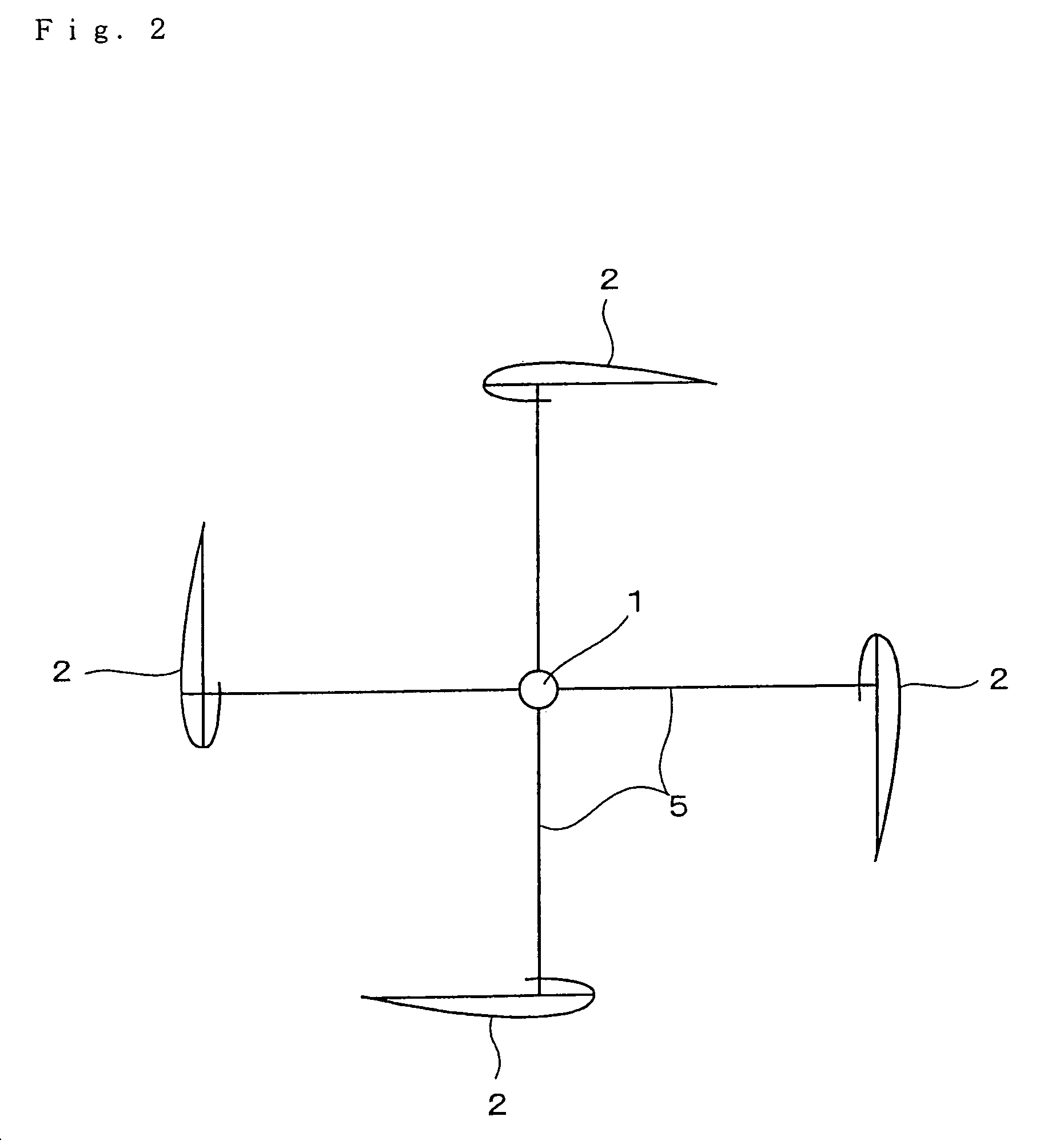
[0022]FIG. 1 shows a windmill A for wind power generation according to an embodiment of the invention. The windmill A is a vertical shaft type windmill for generating power by utilizing a rotational force of the windmill by wind power. As shown by FIG. 1 and FIG. 2, the windmill A is arranged with blades 2,2 . . . of a four sheets blade type comprising an aluminum alloy, plastic including FRP) or the like in parallel with a rotating shaft along a direction of a circumference of the same radius in a face orthogonal to the rotating shaft 1 extended in a vertical direction. As shown by FIG. 3, an outer skin of the blade 2 is formed in a blade type having a streamline shape by bending a material of a thin plate shape comprising a material of an aluminum alloy, plastic (including FRP) in a one sheet structure.

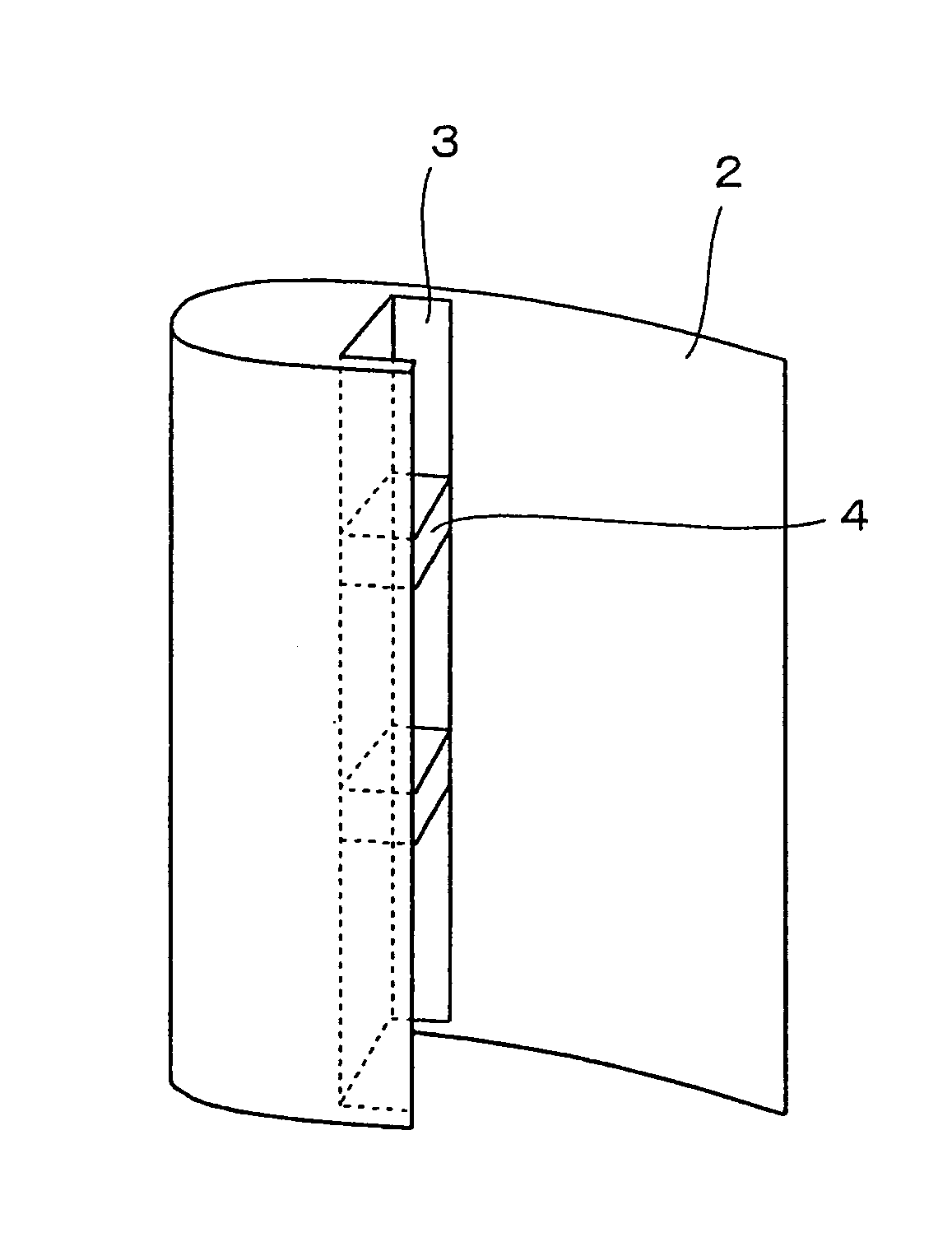
[0023]Further, as shown by FIG. 3 and FIG. 4, a support beam 3 having a section subs...


PUM


Abstract

A windmill for highly efficient wind power generation is provided by enabling one to efficiently rotate the windmill even in starting or at a low wind speed region by improving a blade of a vertical shaft type windmill of a lift type. In the windmill for wind power generation, a plurality of blades are provided in parallel with a rotating shaft in a face orthogonal to the vertical rotating shaft at constant angles centering on the rotating shaft, wherein the blade is of a blade type having a high lift coefficient at low Reynolds number and a notch portion is formed at a rear edge portion of a lower face of the blade.

Description

TECHNICAL FIELD[0001]The present invention relates to an improvement in a shape of a blade of a windmill used for wind power generation.BACKGROUND ART[0002]Generally, in windmills for wind power generation, there are known a horizontal shaft type windmill in which a rotating shaft thereof is made to be horizontal relative to wind as represented by a dutch type windmill and a vertical shaft type windmill in which a rotating shaft thereof is made to be orthogonal relative to wind.[0003]Among them, in vertical shaft type windmills, there are known a drag type windmill in which a windmill is rotated by a drag generated at a blade thereof as in a paddle type, Sabonius type or the like and a lift type in which a windmill is rotated by a lift generated at a blade thereof as in Darrieus type, a gyro mill type or the like. That is, whereas the former rotates the windmill by a drag difference by reducing resistance of the blade directed to the windward, the latter rotates the windmill by the ...

Claims


Application Information

Patent Timeline
Patent Type & Authority Patents(United States)
IPC IPC(8): F01D7/00F03D7/02F03D7/06F03D11/00F03D3/00F03D3/06
CPCF03D3/005F03D3/061Y02E10/74F05B2240/31F05B2240/214F03D3/06
Inventor NOGUCHI, TSUNEO
Owner TAISEI TECHNO
Why Eureka
Try Eureka